Overview
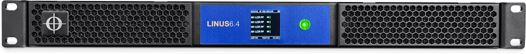
The LINUS6.4 is a four-channel DSP networkable installation amplifier delivering 4 x 1500 W of clean power in a convenient and lightweight 19”/1U package.
Advanced Class D discrete power stages with DC-coupled DACs, together with a high-efficiency SMPS with PFC to provide unrivalled power density and minimal thermal dissipation.
The innovative PCB layout design integrates DSP, four amplifiers, and SMPS on a single PCB for enhanced sound quality, pinpoint control, and rugged protection.
The four audio inputs are selectable, you can choose between analog, LiNET, Dante digital audio network and simply and easily route to any of the four outputs via the input matrix.
The advanced DSP processor enables the integration of sophisticated audio algorithms including phase linear DS-FIR filters, these provide perfect linearity and superior sound performance, plus advanced look-ahead and frequency-dependent limiters. The end result is increased system headroom and sonic fidelity, even under heavy use conditions.
Technical Matrix
| GENERAL | |
|---|---|
| Number of output channels | 4 |
| Output stage | Class D-IC |
| Internal samplerate / bit-depth | 48 kHz / 64 bit |
| Signal-to-noise ratio (22 Hz – 20 kHz, 4 Ω – analogue input) | >105 dB (unweighted) >108 dB (A-weighted) |
| Signal-to-noice ratio (22 Hz – 20 kHz, 4 Ω – digital input) | >113 dB (unweighted) >116 dB (A-weighted) |
| Frequency response (8 Ω load with CLEAR preset) | 20 Hz – 20 kHz = (+0.3 dB /-0.2 dB) |
| THD+N & IMD (4 Ω load @ 1/2 output power) | 20 Hz – 20 kHz = < 0.05% |
| Latency (input to loudspeaker output) | Min. 2.70 ms AES/EBU input Min. 2.00 ms Analog input |
| Protection circuits | Inrush current limiter Thermal limiter Output DC SMPS over-current Output overload |
| LED indicators | Mute status Limit Signal Protection Ethernet connected Power on |
| Ethernet connection | 1 x 100 Mbps RJ45 Control 2 x 1000Mbps RJ45 Dante™ |
| AC Mains | |
| AC mains input connector | IEC |
| AC mains voltage (nominal)** AC mains voltage (maximum)** | 100 V – 240V AC 90V – 264V AC |
| AC mains frequency | 47 – 63 Hz |
| Power consumption* (1/4 power = 200 W @ 4 Ω to represent typical music signal) | Amplifier in standby <= 8 W Amplifier idle <= 23 W Amplifier ¼ power = 1000 W |
| Input | |
| Input sources | Analog, LiNET & Dante™ |
| Analogue input impedance (balanced) | 44 kΩ |
| Maximum input level (analogue differential) | +21 dBu / 8.7 Vrms |
| Input connections | 4x Phoenix 1840379 Analog 1X RJ45 LINET IN (8x CH) 1x RJ45 LINET LINK (8x CH) 2x RJ45 Dante IN (4x CH/optional) |
| Supported digital input formats (internal SRC) | 44.1 kHz / 48 kHz / 88.2 kHz / 96 kHz / 176.4 kHz / 192 kHz |
| Output | |
| RMS output power* (20 Hz – 20 kHz, THD < 0.01%) (all channels driven, 12dB Crest Factor) | 500 W @ 8 Ω 800 W @ 4 Ω 1500 W @ 2 Ω 1600 W @ 8 Ω bridged 3000 W @ 4 Ω bridged (2ch BTL, 2ch SE) |
| Peak output power* (20 Hz – 20 kHz, 6 dB Crest Factor) (all channels driven) | 1000 W @ 8 Ω / 1600 W @ 4 Ω 3000 W @ 2 Ω 3200 W @ 8 Ω bridged 6000 W @ 4 Ω brided (2ch BTL, 2ch SE) |
| Maximum output voltage* | +/- 90 V pk SE +/- 180 V pk BTL |
| Maximum output current* | +/- 50 A pk |
| Damping Factor (8 Ω load, 1 kHz & below) | 2500 |
| Minimum output load | 2 Ω nom SE 4 Ω nom BTL |
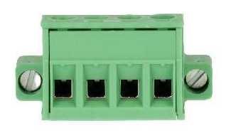
| Power output connections | 2x PHOENIX 4P (Connector supplied with amplifier) |
| Thermal | |
| Operating temperature | +5°C to +55°C 41°F to 131°F |
| Thermal output (BTU/h) | 85.3 = Idle 700 = 20 % 1621 = 50 % 3156 = 100 % |
| Thermal output (kWh) | 0.025 = Idle 0.205 = 20 % 0.475 = 50 % 0.925 = 100 % |
| Cooling | 2x thermally controlled fans Hot air expelled at rear |
| Physical | |
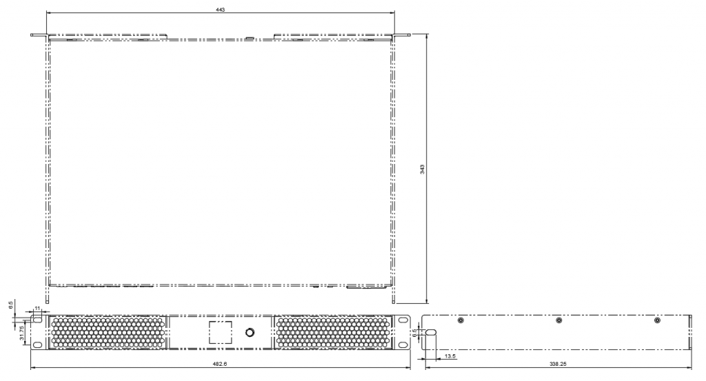
| Dimensions (WxHxD) | 483 x 44 x 345 mm / 19” x 1.73” x 13.58” (1U) (size including back mounting ears) |
| Net Weight | 5.75 kg / 12.68 lbs. |
* Typical values – some variation may exist due to component tolerances.
SE = Single Ended
BTL = Bridge Tied Load
**Voltage range should not be exceeded. Amplifier output power performance will degrade below nominal voltage & increase above nominal voltage.
Amplifier
Signal Inputs
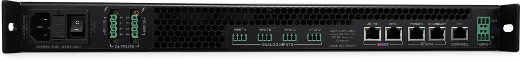
The LINUS6.4/6.4D amplifier offers three different input signal sources:
Analog
In this mode the analog signals connected to the Phoenix input connectors will be used as input signal.
LiNET
With the LiNET setting the input signals are taken from the LiNET Digital Audio interface.
DANTE
With the DANTE setting the input signals are taken from the DANTE Digital Audio Interfaceo.
Analog Input

Phoenix 3.81mm :
Pin 1 = Hot (in polarity, “+”)
Pin 2 = Cold (out of polarity, “-“)
Pin 3 = Ground (chassis/earth)
1 2 3
Always use symmetrically (balanced) shielded cable to connect the amplifier..
LiNET AES/EBU input/output
Eight audio channels are arranged in four AES/EBU pairs. The AES/EBU input and output connectors allow you to receive and send multichannel digital audio streams to other AES/EBU-compatible devices (like other LINUS6.4/6.4D amplifiers for example). Please note that although the AES/EBU and Ethernet connectors use the same connector type (RJ45), the physical transmission protocols are different. So any direct connection between the AES/EBU connectors and standard Ethernet connectors will not work.
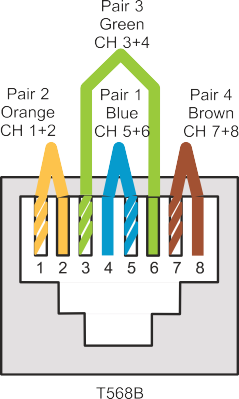
LiN | iETAES/EBURJ45 | pin wiring |
RJ45-Pin | Colour | Channel (polarity) |
1 | orange-white | 1/2 (+) |
2 | orange | 1/2 (-) |
3 | green-white | 3/4 (+) |
4 | blue | 5/6 (-) |
5 | blue-white | 5/6 (+) |
6 | green | 3/4 (-) |
7 | brown-white | 7/8 (+) |
8 | brown | 7/8 (-) |
.
Dante
The DANTE Primary / Secondary connector (LINUS6.4D only) allows you to receive unicast or multicast digital audio streams from any DANTE enabled transmitter. Please note, that LINUS devices are only receivers and therefore third-party software and hard- ware is needed to build a DANTE network. For further information regarding DANTE please visit www.audinate.com.
Remote control inputs (Ethernet/PoE)
The Ethernet link network connector allows you to access the LINUS6.4/6.4D from a host computer for remote control, firmware update and downloading DSP presets. Please note that for setting up proper network connection you need to use the CODA Audio LINUS Control software.
The ethernet link supports PoE (Power over Ethernet) IEEE 802.3af (15.4W). Feeding PoE power to the control port of Linus 6.4 will keep operating the control and dsp section of the Linus 6.4 in case of losing mains power. After the mains power comes back online withing range, it will take only 3 seconds until the amplifer outputs audio again.
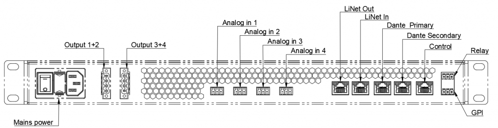
Power outputs
Phoenix Connection. Phoenix Output 1 connector is connected to the channel 1 and 2 amplifier outputs. Phoenix Output 2 connector is connected to the channel 3 and 4 amplifier outputs.
The pin configuration of the Phoenix connectors is as follows:
|
| Normal mode | Bridge mode |
Output 1 | Pin 1 | Channel 1 + | Channel 1 + |
Pin 2 | Channel 1 – |
| |
Pin 3 | Channel 2 + |
| |
Pin 4 | Channel 2 – | Channel 1 – | |
Output 2 | Pin 1 | Channel 3 + | Channel 3 + |
Pin 2 | Channel 3 – |
| |
Pin 3 | Channel 4 + |
| |
Pin 4 | Channel 4 – | Channel 3 – |
GPI Remote control
Pin 1 = Common
Pin 2 = GPI1 (5-24V to activate, unipolar) – Default function = Mute ALL ON upgoing, Mute ALL OFF downgoing
Pin 3 = GPI2 (5-24V to activate, unipolar) – Default function = Standby ON upgoing, Standby OFF downgoing
1 2 3
Relay Remote Control
Pin 1 = Common
Pin 2 = Normally Open – Default function = Contact closes when amplifier stage is running OK
Pin 3 = Normally Closed – Default function = Contact opens when amplifier stage is running OK
1 2 3
Operation
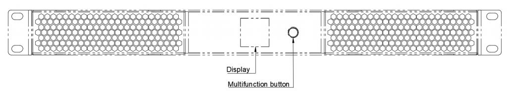
Front panel user interface
The front panel user interface of the Linus 6.4 is a display of 240×240 pixel full color IPS LCD with a wide viewing angle in conjunction with a multifunction illuminated button.
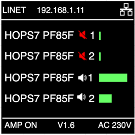
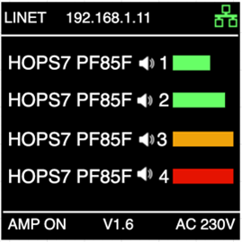
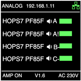
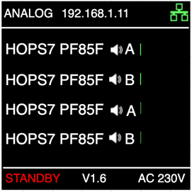
Home Page
The top of the display indicates the network connectivity status.
The center of the display indicates the audio related settings and output level. The speaker icons next to the channel name indicate mute or unmute.
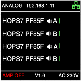
The bottom part of the display shows device status information such as mains voltage, amp stage status and the software version.
Network status
The network icon on the right top of the display indicates if the control network connector is connected.
White indicates the control network is not physically connected.
Green inidicates the control network is connected.
Further the IP address is shown as well as the address assignment type (DHCP or STATIC). Linus Control only uses static IP addressing.
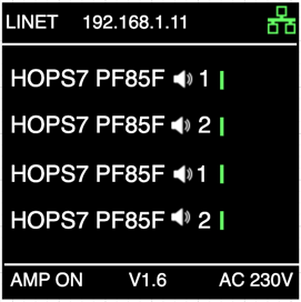
Audio level indicators
Each amplifier channel has a output level bar. The color of each of the level bars can be green, yellow or red.
Green: normal operation
Orange: there is -1 dB of gain reduction (limiting)
Red: there is -3 dB of gain reduction (limiting)
If one or more channels is limiting 3dB, the multifunction button will also flash red.
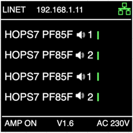
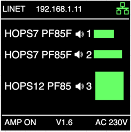
LINET Signal input
The LINUS6.4 has offers 8x LINET input signal channels (AES/EBU). The input Channel is displayed between the mute symbol and the output meter.
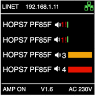
Additional Symbol description
Summed Signals are displayed with an “Exclamation Mark”!
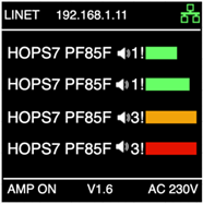
Lost LINET signals (AES/EBU clock not locked) are highlighted with red
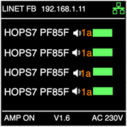
LINET with activated Analog Fallback option “FB” and analog signal input character following the LINET input signal channel
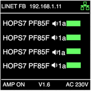
LINET with activated Analog Fallback option “FB” and analog signal input character following the LINET input signal channel -> Red characters indicate a lost LINET (AES/EBU) Clock, input channel receive Audio from analog input signal channel
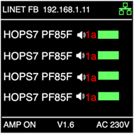
LINET with activated Analog Fallback option “FB” and analog signal input character following the LINET input signal channel -> Orange characters indicate locked LINET (AES/EBU) Clock, input channel receive Audio from analog input signal channel.
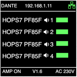
DANTE Signal input
The LINUS6.4 iD includes a DANTE Card with Primary/Secondary connection. Activated DANTE Source indicated as following
Analog Signal input
Analog inputs selected
Additional symbol description
A! Summed Analog input channels
C- Polarity reversed at Analog Input channel C
Normal or bridge mode
The LINUS6.4 has 4 amplifier channels. Alternatively each channel pair (1-2 and/or 3-4) can be bridged to become a higher powered channel by combining 2 channels. This wil double the output voltage.
The image on the right shows channel 3-4 set in bridge mode, while channel 1-2 are in normal mode.
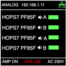
Average power limit
Linus 6.4 has a very high dynamic headroom required by musical signals. The amplifier continuously calculates the average current of all channels and will limit the average power if exceeded.
On the image on the right you see this will be indicated by “AVG LIM” in red on the bottom of the display.
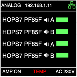
Overtemperature
In case of the internal measured temperature goes above 70degC, a thermal limiter will become active. The amplifier will stay operational, but a gain reduction of 20dB will be applied until the temperature is again under maximum threshold.
The image on the right shows this will be indicated by “TEMP !” in red on the bottom of the display.
Standby
Amplifier has been switched into standby operation (with LINUS Control or 3rd Party commands). Amplifier power supply is turned off and delivers no output
Power over Ethernet (PoE)
Amplifier’s ethernet port is connected to a PoE network switch and the main power supply is detached or switched off (with the switch on rear side of the unit)
Manual Mute
A short press of the multifunction button will mute all channels and will flash the button in green color. Pressing the button again will unmute all channels and the buttons will become steady green again
Power Amp Protection
DC Protection
Each output of the power amp is constantly monitored for persistent DC voltage levels. If the 12 V threshold voltage is exceeded at any of the outputs, the SMPS will be automatically switched off to prevent further damage from overload to the power amplifier and speakers. In this case, the system restarts and tries to readjust the DC parameters. If this does not succeed after the third run, it switches to a permanent error. A DC issue can be located in the output stage, the driver stage, or at the input of the amplifier.
Mains Protection
Inrush current lmitation
Within one second of the LINUS6.4/6.4D amplifiers being connected to the mains, the mains current limiter will charge the capacitors in a controlled way, limiting the maximum mains current during startup. This current is never higher than the maximum peak current in operation.
Mains overvoltage detection
The mains voltage is continuously monitored by the SMPS. If the mains input voltage exceeds 265 V, the main power supply switches off. It will switch on again after the voltage is back within specified range.
Main SMPS protection
Overcurrent protection
The main SMPS (Switched Mode Power Supply) transformer current of your LINUS6.4/6.4D amplifier is continuously monitored. If overcurrent occurs, the main SMPS will limit the current. Should there be an internal failure, this feature prevents other parts from being damaged.
Overload Protection
The output stage is permanently monitored for possible overload situations. There are varying limiting levels of the
look-forward overload protection depending on connected output load. These limits will be set automatically from a load measurement on each output channel. This improves reliability without degrading sound quality when driving complex loads. In case of extremely high output levels with heavily clipped output signals and low loudspeaker impedances < 2 Ω or < 4 Ω in bridge mode, this additional protection will reduce the amplifier stage output power very quickly. If activated, this indicates that the amplifier is running close to its absolute maximum power capacity and the limit LEDs on the front panel are flashing.
In normal operation (no limiting) this protection should never be activated.
Thermal Protection
The temperature of the main SMPS transformer of your LINUS6.4/6.4D amplifier is permanently monitored. If the temperature exceeds 70° C/158° F, a thermal limiter will act on the total system power and avoid a SMPS shutdown.
Fans
The fans mounted in your LINUS6.4/6.4D amplifier operate permanently, but as long as the temperature remains below 40°C /104°F, they will run at their slowest speed. The highest detected temperature from the heatsinks of each channel and SMPS controls the speed of the fans. Above 40°C/104°F the speed is increased until it reaches its maximum value.
Performance
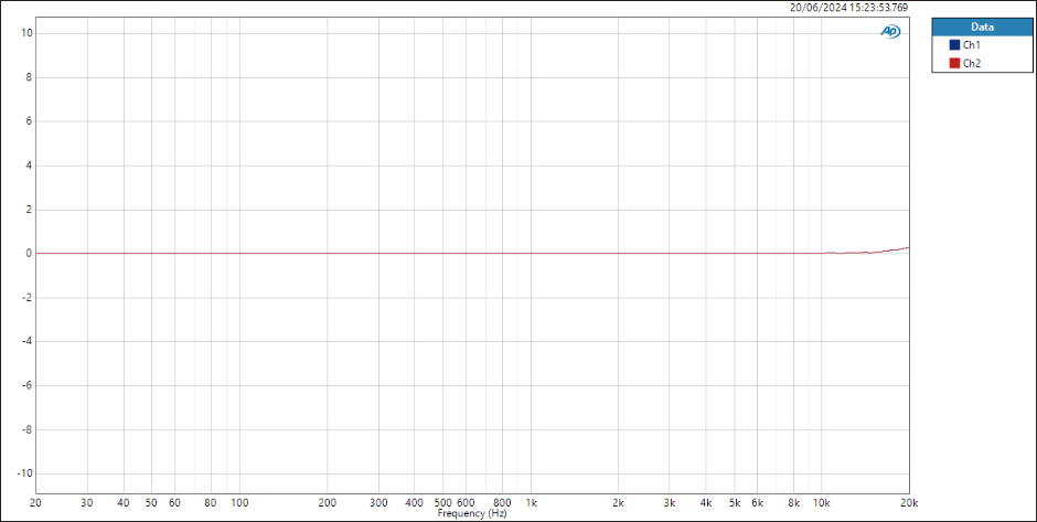
Figure 6.1
FR w/AES17-filter @8Vrms, 4 Ω
(measurement of a typical performance)
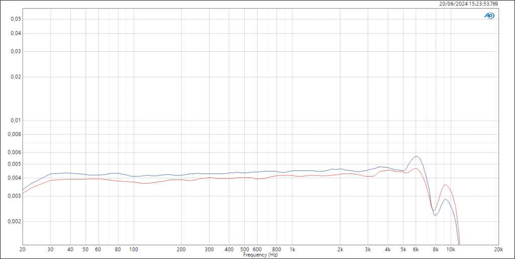
Figure 6.2
THD w/AES17-filter @ 20 Hz –> 20 kHz, 8Vrms, 4 Ω
(measurement of a typical performance)
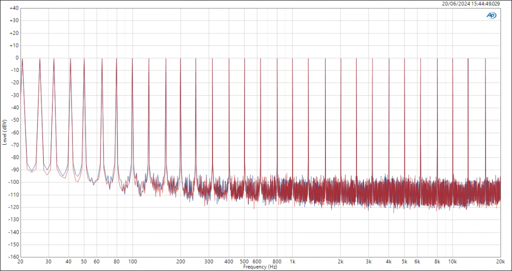
Figure 6.3
IMD spectrum w/AES17-filter @ APx 32 Multitone, total test signal amplitude 18Vp, 4 Ω (measurement of a typical performance)
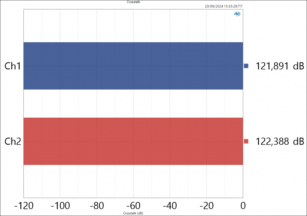
Figure 6.4
Channel separation OR crosstalk @ 1Khz (measurement of a typical performance)
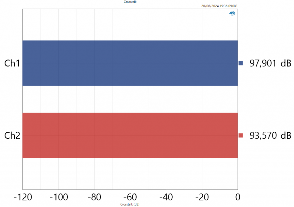
Figure 6.5
Channel separation OR crosstalk @ 10Khz (measurement of a typical performance)
Installation
Mounting
Use four screws and washers when mounting the amplifier to the front rack rails. For mobile use, the amplifier should also be secured using the 19” mounting elements on the rear panel.
Cooling
Under normal operation of the power amp, overheating should never be a problem. The air is taken in from the front and out through the back. It is of course essential that, while the power amp is running, the air is able to circulate freely. The efficiency of the cooling will depend on both the immediate environment (e.g. an enclosed rack, direct sunlight) and if the front filter is clogged. If the amp is installed in a case, the open area at the back of the case must be at least 100 cm². This area should be in line with the amp. Always keep 1HE rack unit space open between adjacent amplifiers.
Mains
Mains Supply
Only connect the LINUS6.4/6.4D amplifier to an appropriate AC circuit and outlet in accordance with the requirements indicated on the rating plate. Only use the supplied mains cable which is supplied with the amplifier for safety reasons.
The LINUS6.4 is shipped with an EU Style Schuko connector, which must be protected by a 16A mains circuit breaker. It must be protected with a 30 A mains circuit breaker. For optimum amplifier output, larger circuit breakers may be used with alternative connectors, please contact CODA Technical Support for guidance.
Please do NOT use much larger mains breakers that recommended here and especially do NOT connect several LINUS6.4/6.4D amplifiers to one single (very large) breaker.
Always respect this rule of thumb for good installation practice for guaranteeing long term reliable, robust and safe operation: one LINUS6.4/6.4D – one circuit breaker.
As soon as the amplifier is connected to mains, the primary capacitors are charged through the inrush current limiter. At the same time the auxiliary power supply is activated, powering the main controller and the display. This allows powering up the main SMPS from the switch on the amplifiers front panel.
Attention: Never unplug the IEC connector while the amplifier is playing music. Always turn the amplifier off from the rear panel switch before disconnecting the IEC connector.
Alternatively, you can disconnect the amplifier from the mains via an external all-pole disconnection (e.g. mains breaker).
Disconnect the mains cable during a lightning storm or when the amplifier remains unused or unsupervised for a prolonged period of time. If a power cut occurs while the amplifier is switched on, it will restart automatically once the mains distribution has been restored. All settings prior to the loss of power will be maintained.
Inrush current limitation
The LINUS6.4/6.4D SMPS uses a processor which always limits the mains inrush current. This limiter will take action under any of the following conditions::
– when connecting the amplifier to the mains through the mains cable
– when switching the amplifier on through an external mains breaker
– the mains voltage was lost (e.g. a short voltage drop).
– This limiter will confine the mains current to a value smaller than 16 Arms*.
*Maximum rms value of inrush current over one half-cycle of the mains voltage according to IEC/EN 55032:2016-02
(Electromagnetic compatibility of multimedia equipment – Emission requirements: German version EN 55032:2012/ AC:2013).
NOTE: Even under normal conditions the mains current can reach levels up to 12 A/32 A (240 V/100 V) and even higher for very short periods of time. This could cause lamps to flicker if connected to the same mains as the amplifier. The impedance of an AC circuit should be less than 0,157 Ω to avoid flicker according to EN 61000-3-11 “Electromagnetic compatibility –
Part 3-11: Limits – limitation of voltage changes, voltage fluctuations and flicker in the public low-voltage supply systems – Equipment with rated current ≤ 75 A and subject to conditional connection” (IEC 77A/929/CDV:2016).
If in any doubt, consult your local power provider. Never attempt to measure this impedance level with your Ωmeter. This may damage your meter and expose you to the risk of electric shock.
Mains power consumption and power draw
Due to the huge output power of the LINUS 6.4/6.4D, the mains current draw can get very high when demanding large output powers. Please refer to following table for an overview of mains currents and power consumption under different operating conditions.
Operating condition |
Mains current (4 Ω) |
Power consumption (4 Ω) |
Output power (4 Ω) |
Amplifier standby (output stage off) |
0.20 A |
8 W |
0 W |
Idle (power on) |
0.40 A |
22 W |
0 W |
100 W per channel / 1/8th |
2.30 A |
500 W |
400 W |
200 W per channel / 1/4th |
4.30 A |
1000 W |
800 W |
250 W per channel / 1/3rd |
6.10 A |
1200 W |
1000 W |
Mains current draw and power consumption @ 230 V, 50 Hz.
Measured with pink noise with crest factor of 12 dB to present typical music signal. For 115 V mains operation, the current values can be multiplied by 2.
Please note that the values given here are typical values only, measured on a standard 230 V/50 Hz outlet. The actual mains current draw can vary depending on the music signal and the mains characteristics (especially the mains impedance) of any specific installation.
Maintenance information
Cleaning and servicing work on the inside of the amplifier must only be carried out by qualified personnel.
Qualified personnel is defined as a person who has gained specialised relevant knowledge of electronic engineering through education, training, and experience, and who has sufficient knowledge of all relevant governmental work safety regulations to be in a position to judge the safe functioning of power amplifiers based on technical rules according to IEC/ EN 62368-1:2018 (“Safety Requirements for Audio, Video or similar Electronic Appliances”).
In order to guarantee the safe functioning of the amplifier, it has to be checked regularly, depending on its application but at least once a year, by a properly qualified person.
Advice on how to carry out these checks can be found in DIN VDE 0701-0702:2008-06 “Safety Checks for Electronic Appli- ances” . An amplifier that is considered to be unsafe must be labelled accordingly and stored in a safe place to prevent this amplifier being used mistakenly.