1. Why cardioid?
Cardioid system configurations are sometimes very useful for:
- reducing diffused energy, providing a more direct and precise signal reproduction towards the listening environment.
- steering radiation patterns; in turn reducing interaction between adjacent system elements.
- rejecting energy towards noise sensitive areas, whilst simultaneously maintaining high pressure in other areas.
It stands to reason that this is why cardioid subwoofer & line array configurations are quickly gaining popularity. For these reasons, CODA Audio presents in this document several cardioid setups for its range of subwoofers, together with tried and tested tactics to implement cardioid radiation patterns for its line arrays.
2. Subwoofers
2.1. Subwoofer types
When it comes to dispersion, there are generally two types of subwoofers:
Adaptable/Versatile subwoofers:
- Generally, these are front-loaded subwoofers.
- The user can decide to use the same subwoofers in omnidirectional, cardioid, end-fire or other setups, depending on the application.
- These offer greater flexibility than a ‘cardioid only’ subwoofer.
Cardioid subwoofers:
- Typically, these are front and rear loaded subwoofers, where two or more drivers are placed in the front and rear of the same enclosure.
- More often than not, two or more channels of amplification are required to drive these drivers independently.
- These subwoofers always radiate a cardioid pattern – an omnidirectional pattern is not usually possible.
2.2. Why does CODA Audio not produce cardioid-only subwoofers?
Simply put, there are too many situations where you can’t use cardioid subwoofers.
2.3. What’s the main limitation of cardioid-only subwoofers?
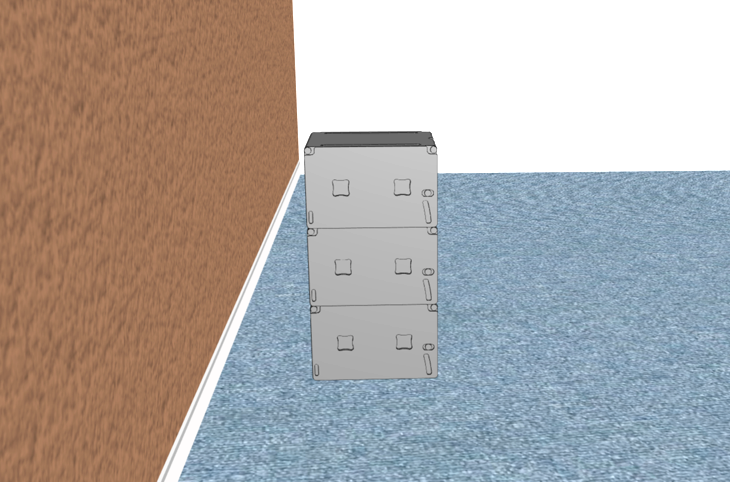
As cardioid-only subwoofers typically have rear-loaded drivers, most manufacturers correctly mandate that a gap should be left behind the enclosure when placed near walls or other boundaries, especially solid walls, to allow for proper operation – [Figure 1]. Unfortunately in many venues, this gap is impractical and not possible, so the subwoofers end up being placed against the walls, drastically jeopardising efficiency.
2.4. What happens when a subwoofer – omni or cardioid – is placed near a wall?
The gap behind the subwoofers creates a massive degradation in frequency response caused by a comb filter, which is shown below. This effect is observable with both omnidirectional and cardioid-only subwoofers, albeit to a slightly lesser extent.
 |
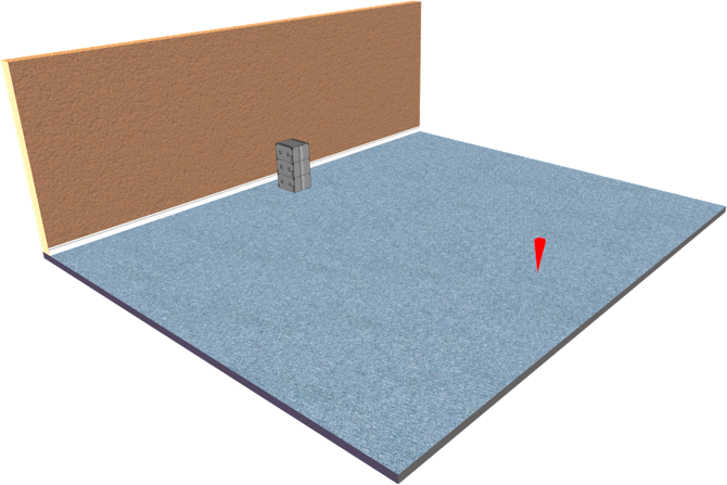 |
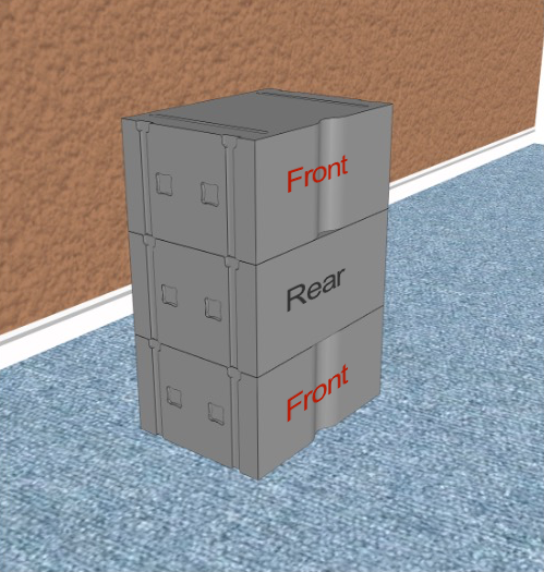
| [Figure 1] – A subwoofer arrangement, with a 0.6m gap to the rear. | [Figure 2] – Measurement position for frequency response shown in [Figure 3]. |
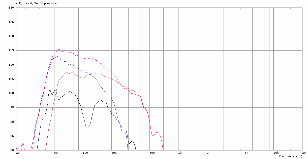
This comb filter is a result of the destructive interference caused when the energy radiated backwards from the subwoofer is reflected by the wall towards the listener. This energy sums with the forward radiating energy from the subwoofer, causing a frequency response similar to that shown below in [Figure 3].
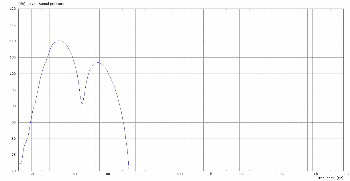
The frequency of this first cancellation, shown here at 62Hz, is primarily dependent on the physical size of the subwoofer, in combination with the gap left behind it to the wall.
2.5. Why does this happen?
In this vastly (!) over-simplified example shown below in [Figure 4], it can be seen that the energy arriving at point ‘X’ is the complex summation of the direct energy, shown in green, with the reflected energy, shown in red. When the subwoofer stack is placed with a 0.6m gap behind it, there is a pathlength difference between the direct and reflected energy, which equates to a 180º cancellation at 62Hz.
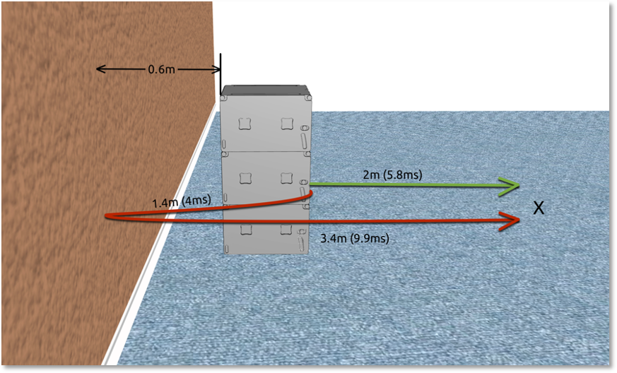
The pathlengths shown in [Figure 4] are summarised in [Table 5]. It can be seen that there is an 8.16ms difference between the arrival of the direct & reflected energy.
This equates to one cycle of 122Hz, where there will be positive summation (witnessed in [Figure 6]), and thus destructive combing will occur at a frequency where 8.16ms is 180º of its wavelength; I.E: 61.25Hz.
| Path | Length | Time |
| Direct (Green) | 2m | 5.83ms |
| Reflected (Red) | 1.4m + 3.4m = 4.8m | 13.99ms |
| Delta: | 8.16ms |
Crucially, it should be understood that this degradation in frequency response exists with both types of subwoofer – omnidirectional (versatile), and cardioid-only. With an omnidirectional subwoofer however, there are options available to the user to mitigate this.
2.6. Wall mitigation 1 – move subwoofers up against the wall
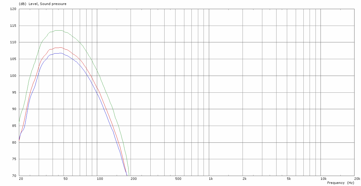
In this first case, the subwoofer can be placed hard up against the wall, (as close as possible, with consideration given to protecting the connectors). This minimises the pathlength delta between the direct and reflected energy, which has the effect of moving the comb filter higher in frequency. The comb filter can be pushed out-of-band, or high enough to not cause a problem. There is a gain in energy below this frequency, due to the efficient coupling with the wall. [Figure 7] shows the result of a stack of 3x omnidirectional SCP-F subwoofers, both placed hard up against a wall (purple trace) – quarter space, and in half space (black trace).
2.7. Wall mitigation 2 – point stack at wall
In this second case, it is possible to limit this interaction further, and gain a further increase in energy. To achieve this, simply spin the stack of subwoofers 180º in azimuth, and point them at the wall. Leave a gap of around 0.3m to 0.5m between the subwoofer face and the wall. In this case, all the energy is in-phase without any cancellations from reflected backwards energy. The energy radiated to the front in this case will be increased by around 6dB, when compared to a half-space measurement.
[Figure 8] shows the results of a stack of 3x SCP-F subwoofers placed in this orientation, with a gap of 0.3m between the face of the subwoofers and the solid wall. The subwoofers are oriented in the omnidirectional configuration. The black trace shows the frequency response in half-space, and the red shows the frequency response against the wall (quarter-space).
2.8. Wall mitigation 3 – corner placement
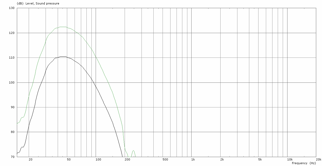
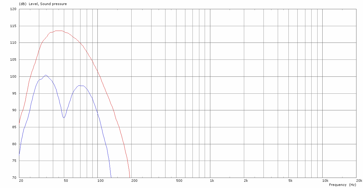
If the corner has solid walls, consider turning a versatile subwoofer into the corner. In this case, the corner itself forms a large horn, which drastically increases the energy radiated to the front. This corner placement offers further benefits, in that it excites all the room modes, providing even dispersion without any hot spots. The corner placement requires less subwoofers to achieve a given SPL and due to this increased efficiency, requires far less amplification power, which is obviously good for the electricity bill. The green trace in [Figure 9] shows the results of a stack of 3x SCP-F subwoofers positioned into the corner of a room, the black trace shows the comparable stack in half-space. A considerable gain is observable.
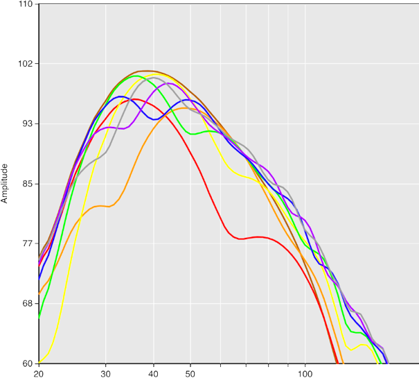
A comparison of all three mitigations is shown in [Figure 10], all comprising 3x SCP-F.
- Black trace – reference half-space measurement.
- Blue trace – subwoofers placed with gap behind against wall.
- Purple trace – mitigation 1 – removing space behind subwoofers and wall.
- Red trace – mitigation 2 – pointing subwoofers at wall.
- Green trace – mitigation 3 – moving subwoofers into corner of room.
Note: In all of these three suggested mitigations for the presence of walls, it is assumed that the walls are
solid, and are quite ‘massive’ – that is, that they have a large mass.
It should be noted that it is not possible to achieve these mitigations to the same effect with cardioid-only subwoofers, only adaptable / versatile subwoofers will allow for these configurations to be successfully deployed.
2.9. So – how can I deploy a cardioid configuration with versatile subwoofers?
Below is outlined three approved methods for building cardioid subwoofer configurations. These methods each have various qualities, some of which are better than others. It is up to the system designer to make an assessment of the configurations, and balance the compromises, to arrive at the correct choice of deployment.
The suggestions to be presented are:
- Standard cardioid array.
- Extended cardioid array.
- Physical end-fire array.
In each suggestion, comparisons will be made in relation to a standard omnidirectional deployment of the same subwoofers. There are several criteria which can be used to judge the performance of these deployments, namely:
- Physical space required:
- The ‘footprint’ of the array.
- Front / Forward SPL:
- The energy projected forwards, towards the audience.
- The criterion that conveys by how much the frequency response will be altered, when compared to an omnidirectional subwoofer configuration.
- It is a qualitative measure of the accuracy / honesty of signal reproduction, to the front of the array, in the magnitude domain.
- Rear SPL:
- The energy projected rearwards, away from the audience.
- Time domain integrity:
- A qualitative measure of the accuracy / honesty of signal reproduction with transient signals.
- Directivity:
- A qualitative measure of the radiation pattern of the configuration.
Note: The ratio of front SPL to rear SPL can be considered the ‘rejection ratio’.
Note: In all following descriptions, a stack of subwoofers is described for simplicity, however this is equally as relevant for flown situations, for example with SCP-F / SCV-F.
2.10. Cardioid configuration 1 – Standard cardioid array
2.10.1. About
The standard cardioid array can be considered the simplest to deploy & configure, and a good all-rounder. This arrangement does not require much more floorspace than a conventional array of omnidirectional subwoofers.
2.10.2. Physical Configuration
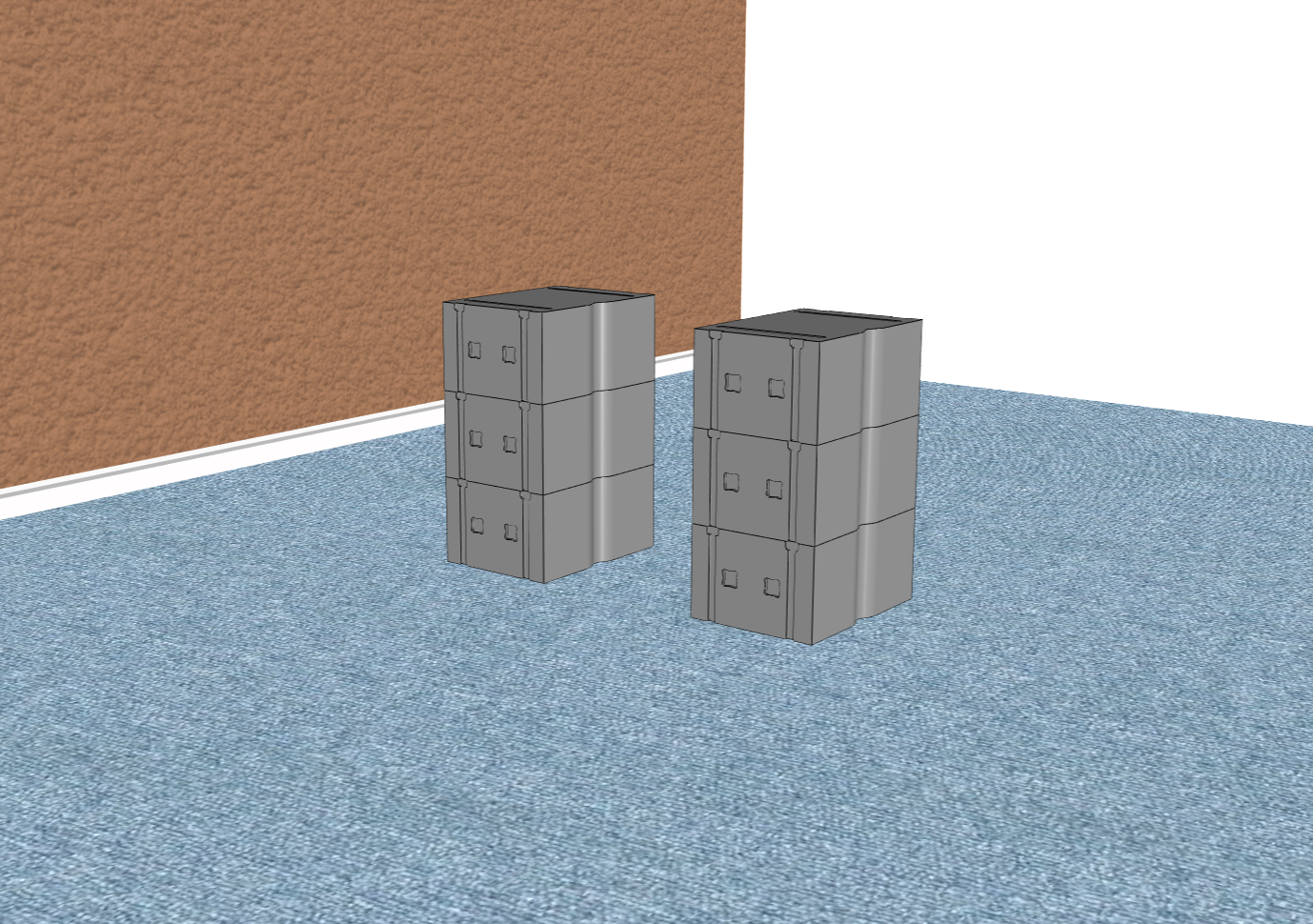
One element within the array of subwoofers is spun 180º away from the audience, as shown in [Figure 11]. This subwoofer that is spun 180º shall be referred to as the ‘rear’ subwoofer. The recommended ratio is 1x rear subwoofer for every 2x or 3x front facing subwoofers.
Note: It is indeed possible to use 1x rear subwoofer for every 1x front subwoofer, but there will be a reduction in maximum achievable SPL towards the front of the array.
A gap of at least 60cm free space is mandatory behind and above the array. A gap of at least 60cm free space should be left either side of the array; however when using multiple stacks of this configuration, a gap of around 30cm will suffice. To achieve results in a confined environment similarly obtainable to that that of free space, a gap of 2m should be left behind, above, and to the sides of the array.
This typically precludes the possibility of placing cardioid deployments of subwoofers under stages, or in walls etc. Consider this article for further reading: http://adamjhill.com/2018/04/25/cardioid-subwoofers-are-claustrophobic/
2.10.3. Electronic Configuration
The cardioid presets within the CODA Amplification platform fall under the subheading ‘Cardioid’ within the loudspeaker list, together with their LPF frequency, and their application- be it ‘Front’ or ‘Rear’. It is important that the front subwoofers are driven with the ‘Front’ preset, and the rear facing subwoofers are driven with the ‘Rear’ preset.
Note: Different LPF frequencies should not be mixed within the array.
2.10.4. Acoustic Performance
2.10.4.1. Front SPL
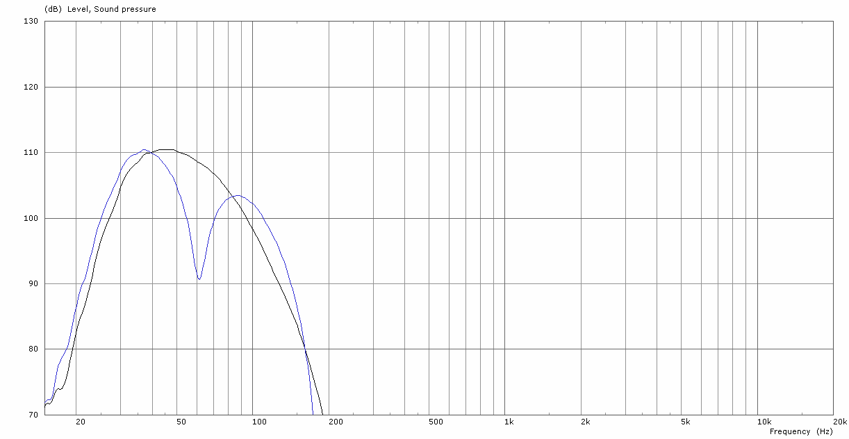
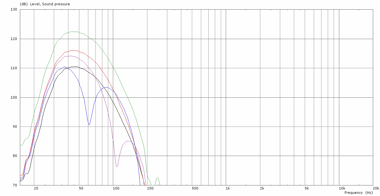
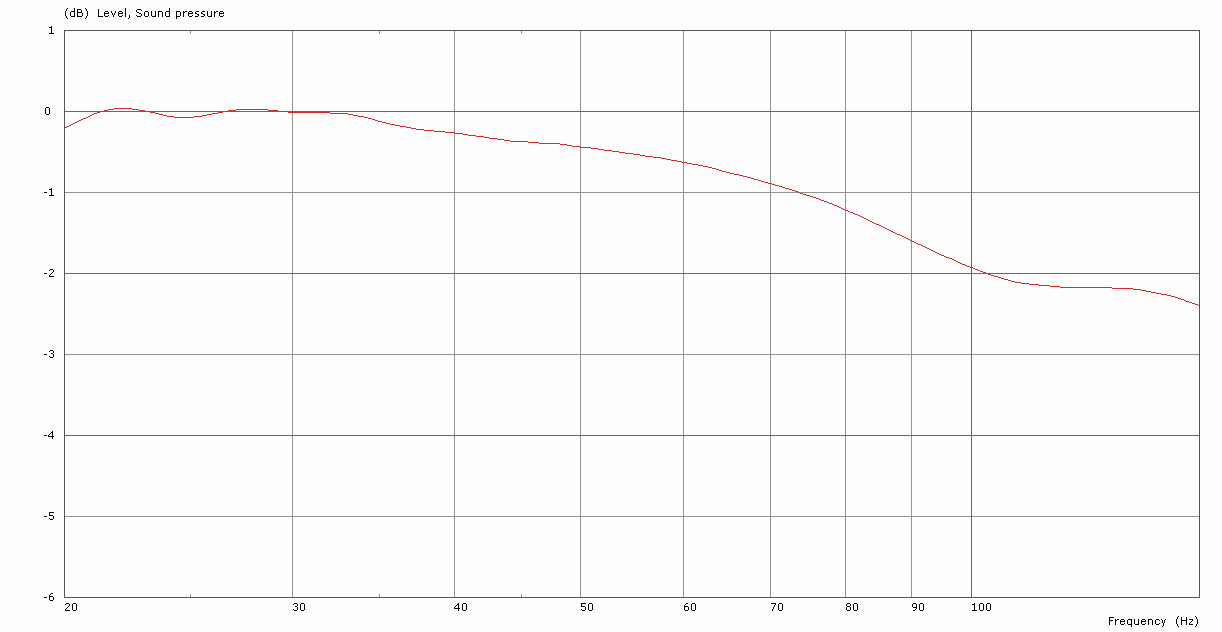
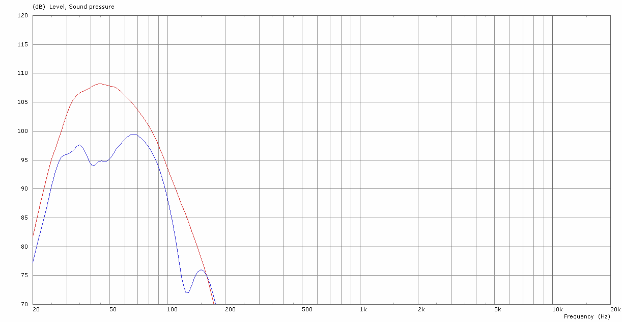
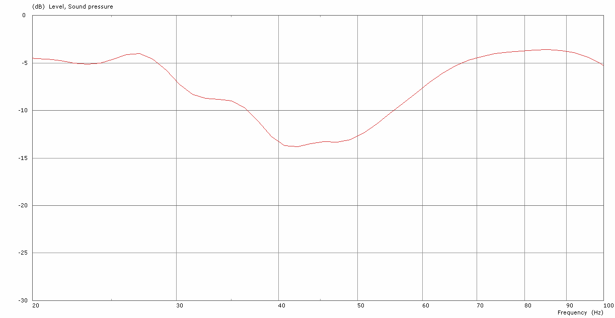
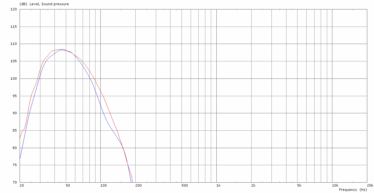
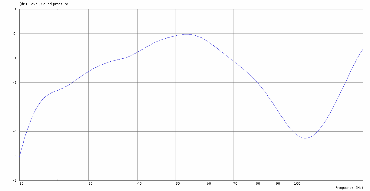
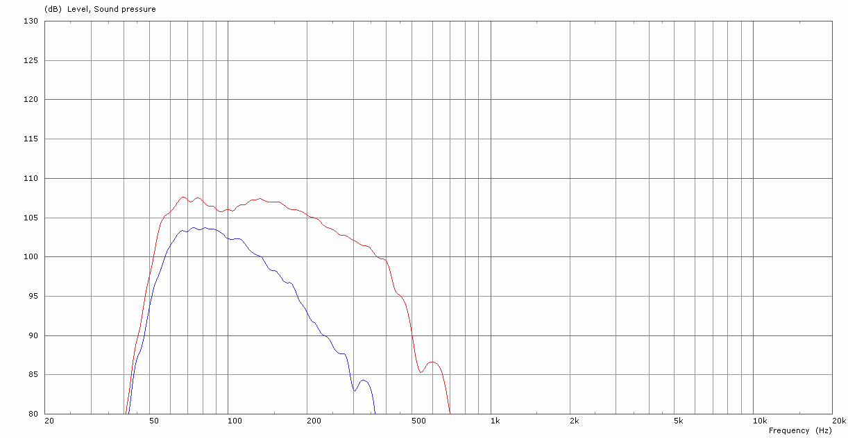
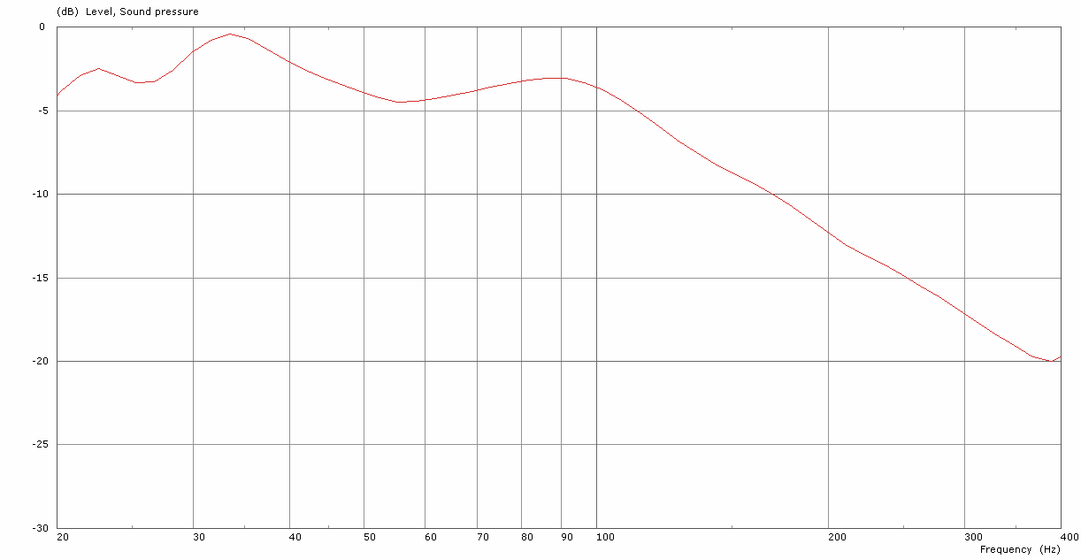
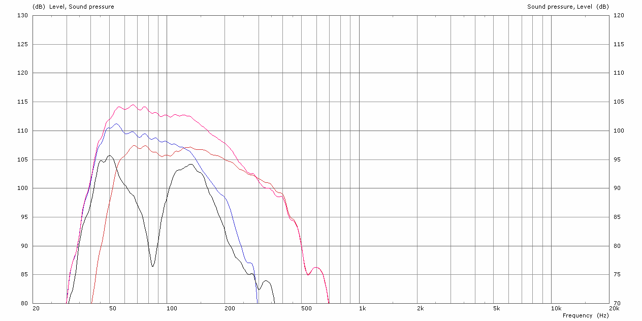
The energy radiated forwards towards the listener is very similar to that of the reference omnidirectional configuration. [Figure 12] shows only a small reduction in pressure in the sub region; – the red trace shows a measurement of 3x SCP-F’s stacked in the reference omnidirectional configuration. The blue trace shows a measurement of 3x SCP-F’s stacked in the standard cardioid configuration. The delta of these measurements is shown in [Figure 13].
2.10.4.2. Rear SPL
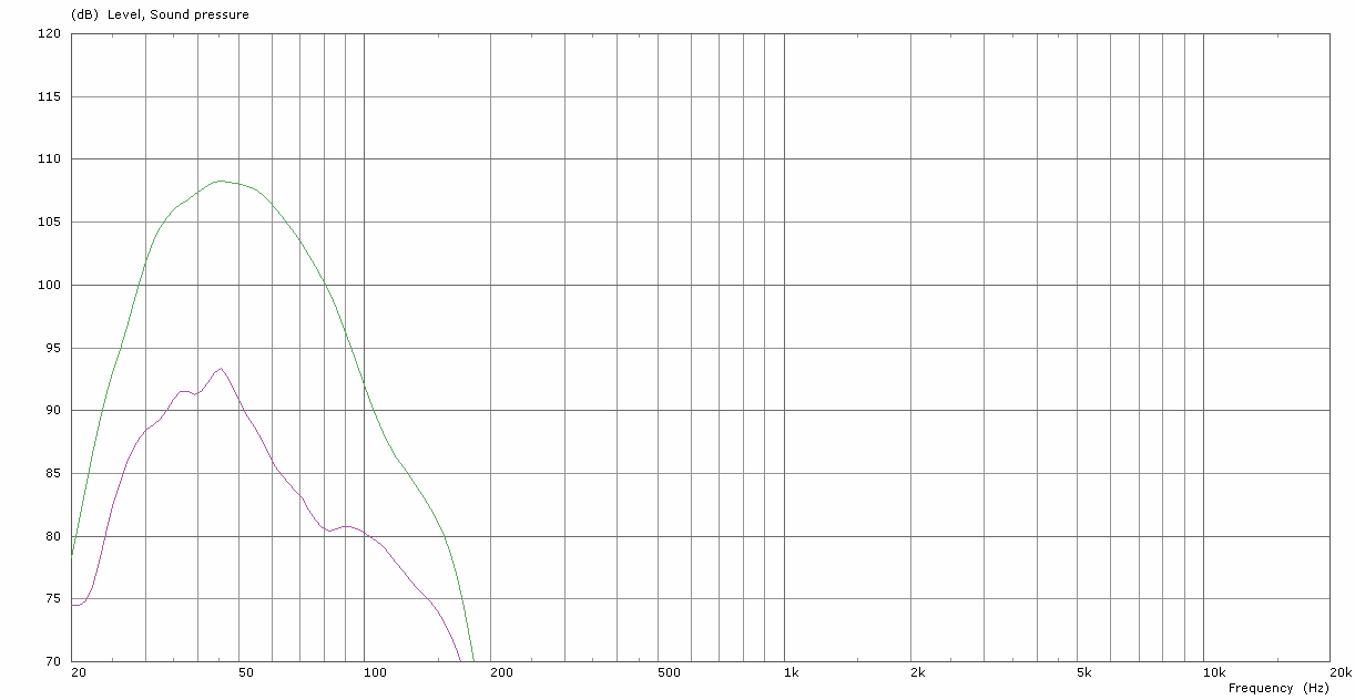
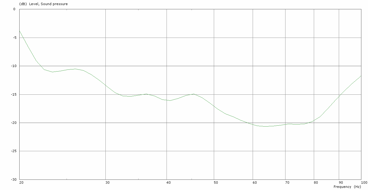
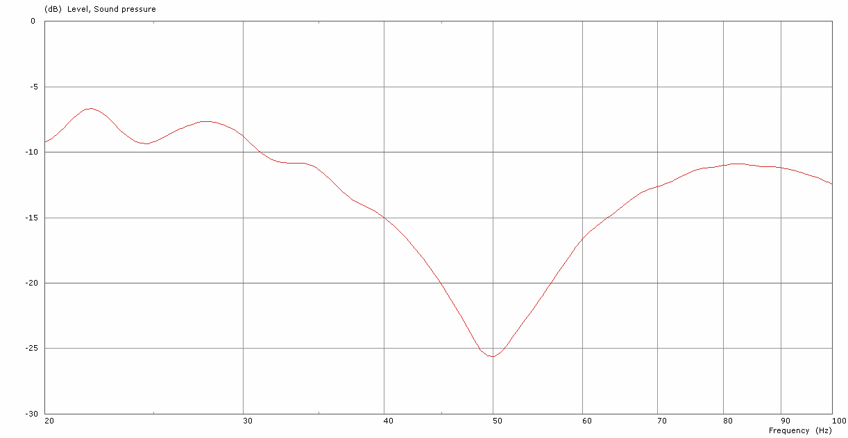
The energy radiated rearwards shows a significant cancellation centred at 44Hz. Above and below this frequency, there is still a reduction – albeit not as deep. [Figure 14] shows 3x SCP-F’s deployed as a ‘standard cardioid’ array – the red trace shows a measurement in front of the array; the blue trace shows a measurement towards the rear. The delta of these measurements is shown in [Figure 15].
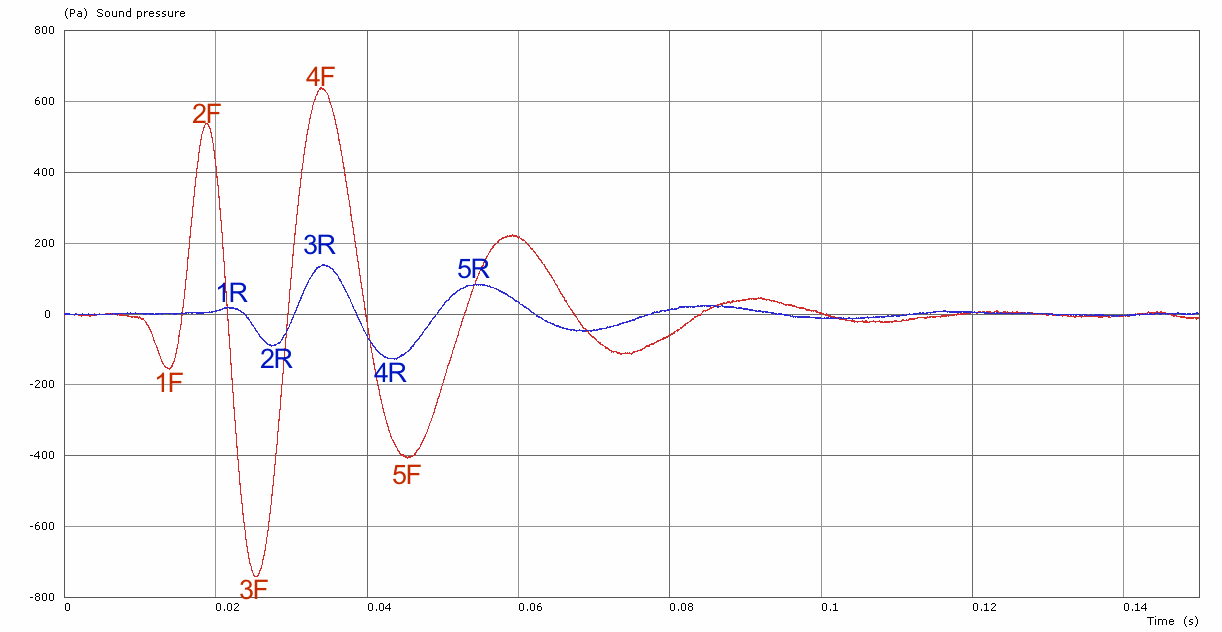
2.10.4.3. Time Domain Integrity
[Figure 16] shows the impulse response of a stack of 3x SCP-F stacked in the standard cardioid configuration, measured 8m in the front of the array. The red trace shows the impulse from only the front facing drivers, the blue trace shows the impulse from only the rear drivers.It can be observed that when measured in this position, both the forwards and rearwards facing drivers have the “peaks” of their impulses aligned in time with each other, producing, subjectively, a “high fidelity & punchy” sound.
2.10.4.1. Directivity
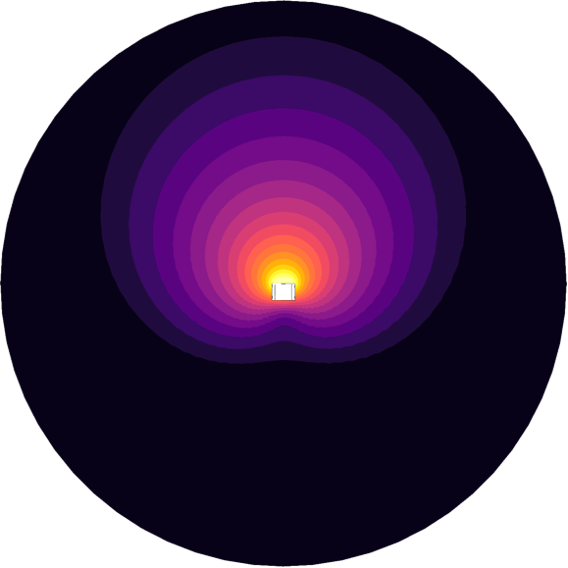
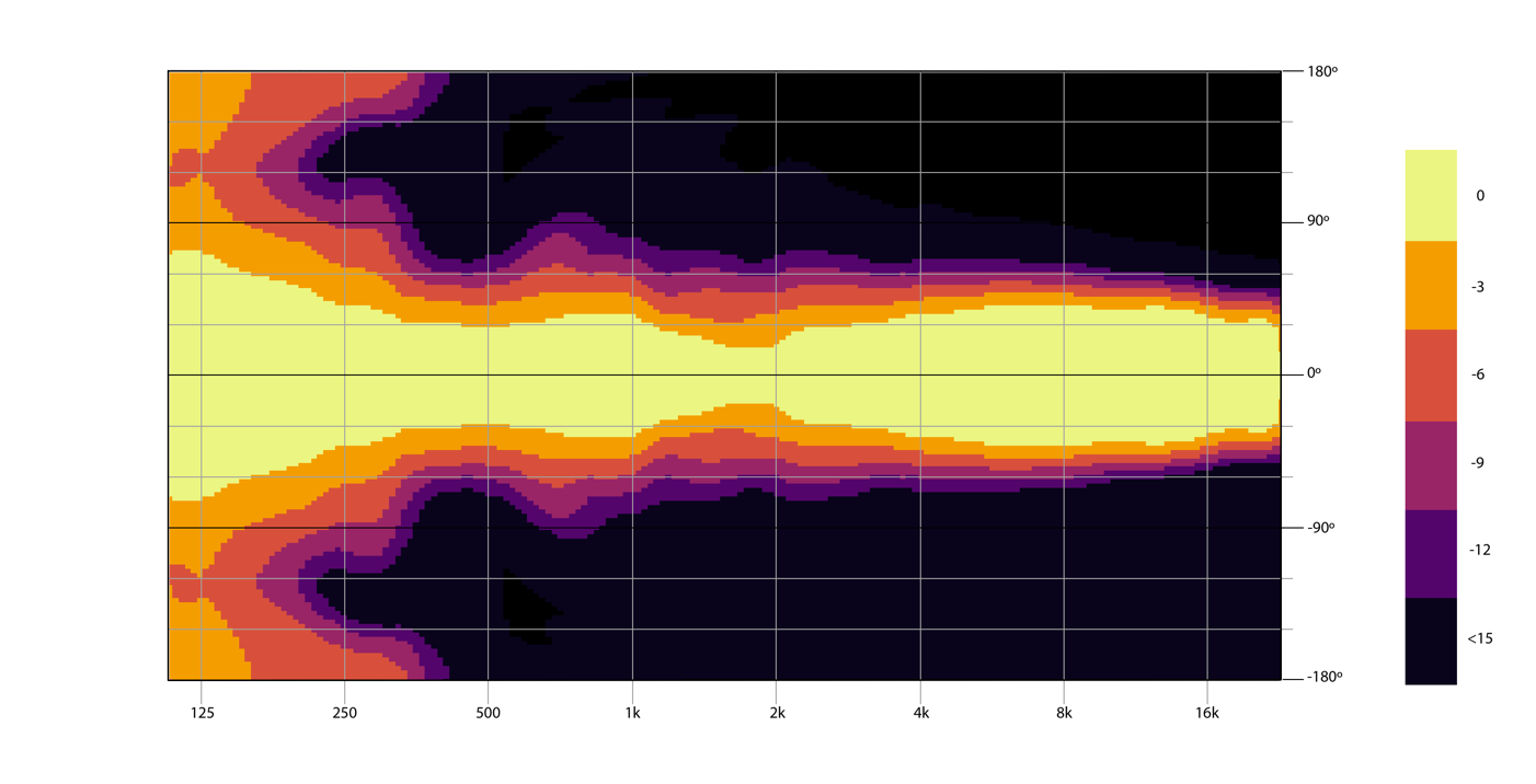
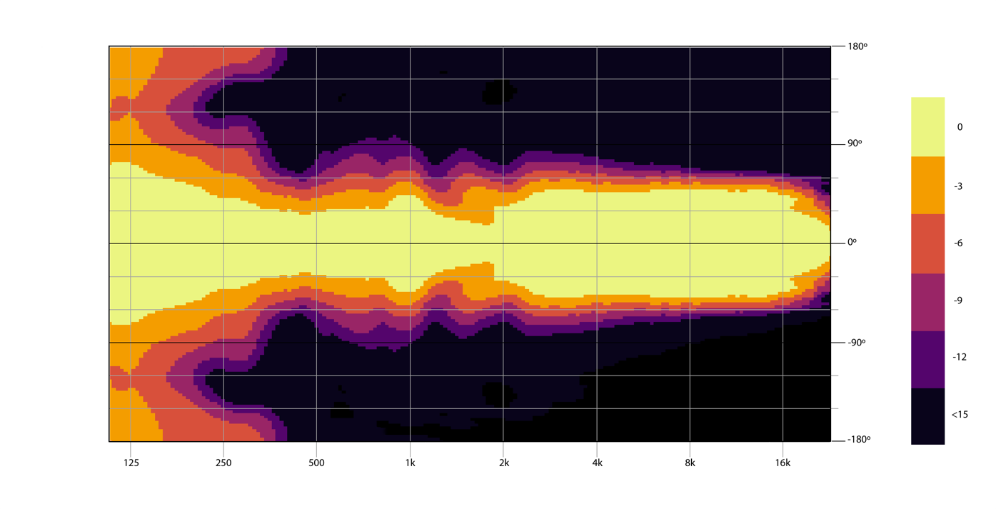
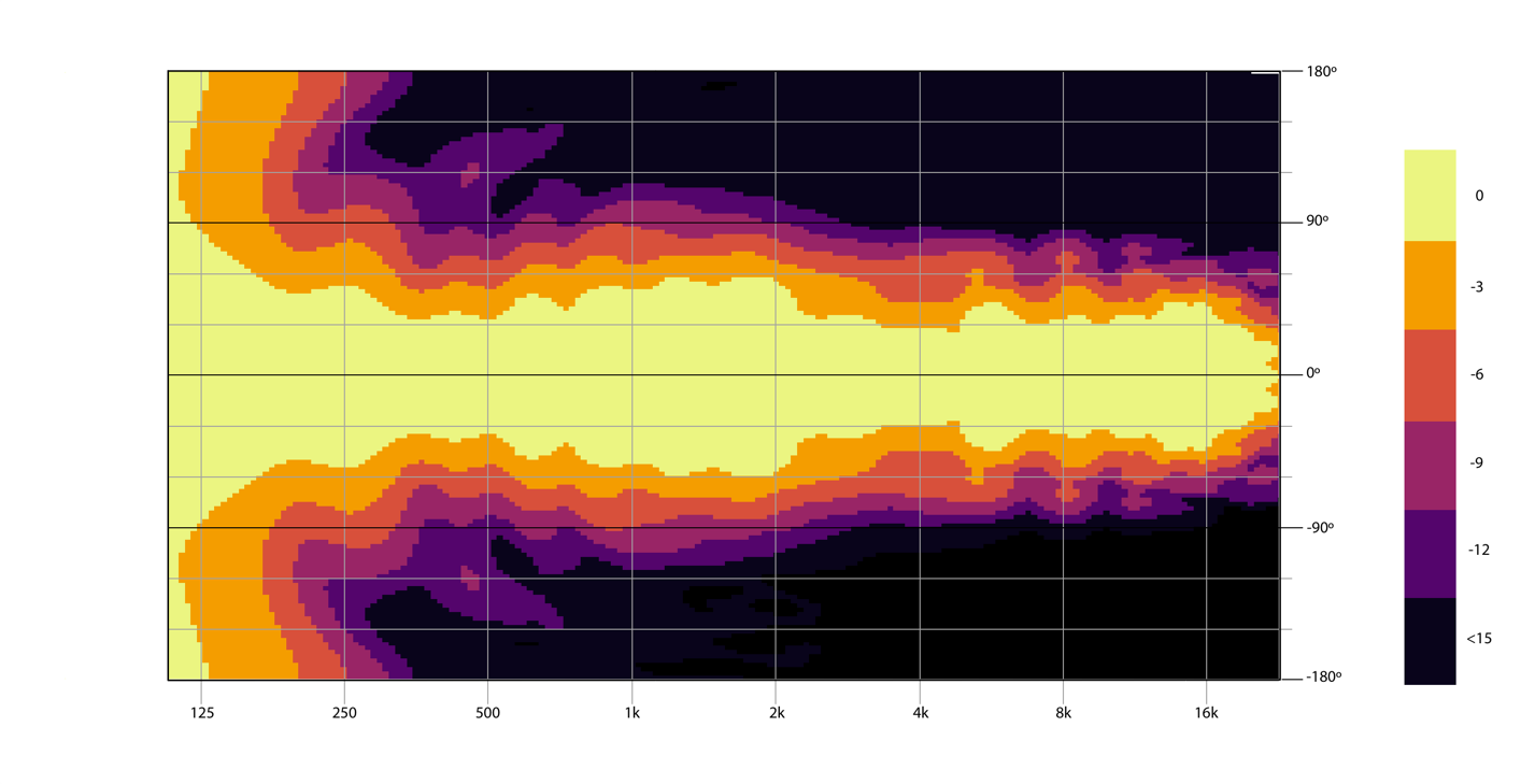
The radiation pattern realised from the standard cardioid array is shown in [Figure 17].
2.10.5. Analysis
When deployed as prescribed, the standard cardioid array yields a large cancellation with only a subtle compromise made in step response integrity in comparison to that of the reference omnidirectional configuration. Furthermore, there is only a small reduction in the higher spectral output from the subwoofer stack, the low frequency output is, to all intents, unchanged. A larger footprint is not required, compared to that of an omnidirectional stack, however caution should be given to placement near walls, as with cardioid-only subwoofers. Overall, this is a solid all-rounder offering reasonable rejection to the rear.
2.11. Cardioid configuration 2 – Extended cardioid array
2.11.1. About
The extended cardioid array looks physically identical to the standard cardioid array, and is as easy to deploy. It however features a completely different electronic configuration & should only be considered when there is an overriding desire to achieve maximum rejection behind the array, knowingly at the detriment to the audio quality towards the listeners.
The SPL achieved towards the front of the array is reduced when compared to that of both the reference omnidirectional configuration & the standard cardioid array. The time domain integrity is also compromised, together with the reproduction of very low frequencies.
These compromises may be considered not a factor when weighed up against its only benefit – the large rejection ratio.
2.11.2. Physical Configuration
As with the standard cardioid array, one element within the array of subwoofers is spun 180º in azimuth away from the audience, as shown in [Figure 11]. This subwoofer that is spun 180º shall be referred to as the ‘rear’ subwoofer. The recommended ratio is 1x rear subwoofer for every 2x or 3x front facing subwoofers.
Note: It is indeed possible to use 1x rear subwoofer for every 1x front subwoofer, but there will be a reduction in maximum achievable SPL towards the front of the array.
A gap of at least 60cm free space is mandatory behind and above the array. A gap of at least 60cm free space should be left either side of the array; however when using multiple stacks of this configuration, a gap of around 30cm will suffice.
2.11.3. Electronic Configuration
In this configuration, the “Extended Cardioid” presets shall be used on all subwoofers within the array, be it with 70Hz, 100Hz (or otherwise) LPF’s. It is crucial the front subwoofers are driven with the ‘Front’ preset, and the rear facing subwoofers are driven with the ‘Rear’ preset.
Note: Different LPF frequencies should not be mixed within the array.
2.11.4. Acoustic Performance
2.11.4.1. Front SPL
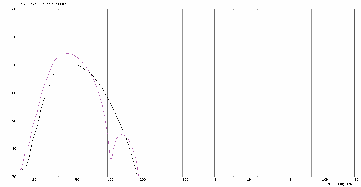
The energy radiated forwards towards the listener is somewhat similar to that of the reference omnidirectional configuration, however of significance, there is a reduction of energy below 50Hz, which has quite an impact on the maximum SPL attainable; & to an extent – the power required to achieve this SPL.
The red trace shown on [Figure 18] is a measurement of 3x SCP-F’s stacked in the reference omni configuration; the blue trace shows a measurement of 3x SCP-F’s stacked in the extended cardioid configuration. The delta of these measurements is shown in [Figure 19].
2.11.4.2. Rear SPL
The energy radiated rearwards shows a significant and even broadband reduction compared to the front. [Figure 20] shows 3x SCP-F’s configured in the extended cardioid array – the green trace shows a measurement in front of the array; the purple trace shows a measurement towards the rear. [Figure 21] shows the delta of these two measurements.
2.11.4.3. Time Domain Integrity
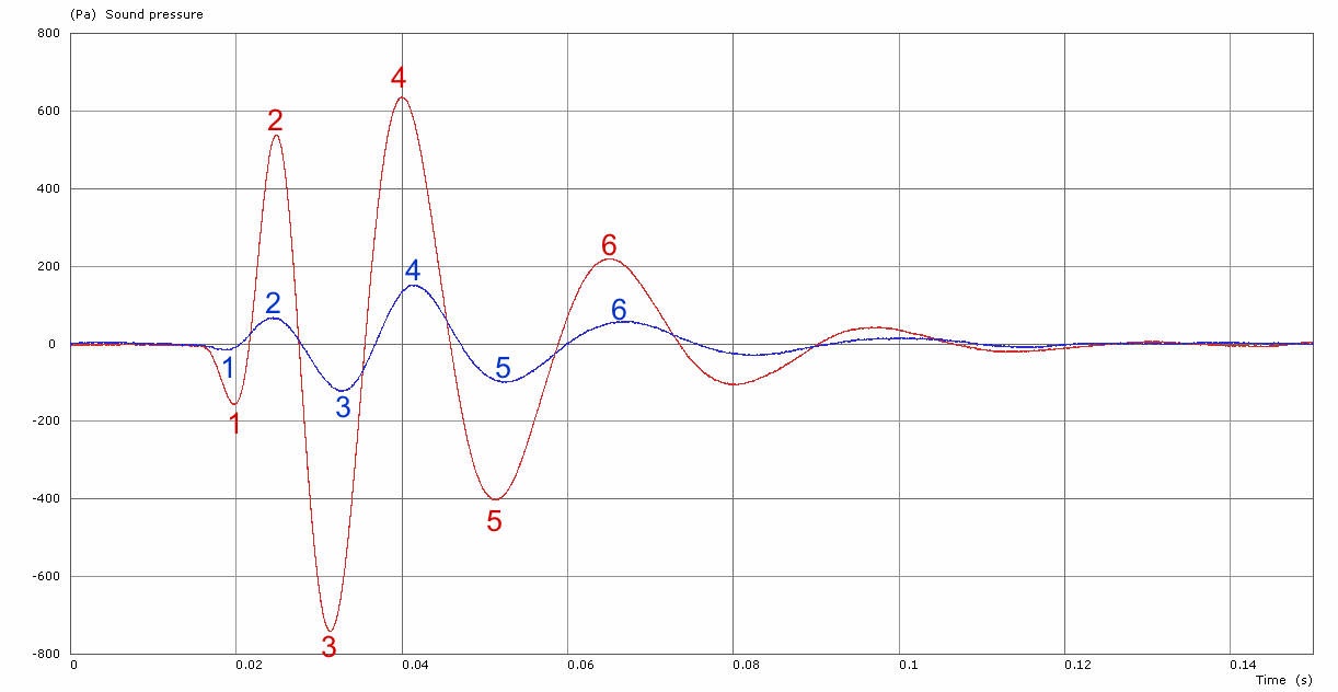
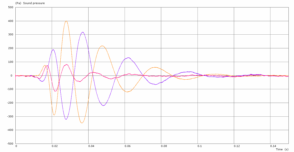
[Figure 22] shows the impulse response of a stack of 3x SCP-F stacked in the extended cardioid configuration, measured 8m towards the front of the array. The red trace shows the impulse from only the front facing drivers, the blue trace shows the impulse from only the rear drivers.It can be seen that the “peaks” of the impulses of the front and rear drivers are found to be out of polarity with each other in the listening area, and are delayed such that the positive-going pressure gradient of the rear driver is rotated in phase the to match the positive-going pressure gradient of the front driver.
[Figure 23] shows the same stack of subwoofers as shown in [Figure 22], however these measurements are all taken to the rear of the stack. The orange trace shows the energy from the rear facing drivers, the purple trace shows the energy from the front facing drivers. The pink trace shows the resultant summation of the energy from the front & rear drivers. It can be seen that the front and rear drivers are successfully working against each other, to massively reduce the pressure behind the array.
2.11.4.4. Directivity
The radiation pattern realised from the extended cardioid array is shown in [Figure 24].
2.11.5. Analysis
When deployed as suggested, the extended cardioid array yields an excellent rejection ratio as shown in [Figure 21]; it is both wide in bandwidth and large in terms of rejection. There is however a compromise in step response integrity & low frequency reproduction, when measured in comparison to both that of the standard cardioid array, and the reference omnidirectional configuration.
A larger footprint is not required, compared to that of an omnidirectional stack, however caution should be given to placement near walls, as with cardioid-only subwoofers.
Overall, this is a configuration that offers vast cancellation to the rear, but it should not be used haphazardly without serious consideration to its drawbacks.
2.12. Cardioid configuration 3 – Physical end-fire array
2.12.1. About
The physical end-fire array requires a larger footprint than either of the previously mentioned cardioid setups, but should be considered if space is not an issue and there is a strong desire to achieve both a high rejection ratio, high front SPL, and a step & frequency response integrity which is unchanged with respect to the reference omnidirectional configuration.
2.12.2. Physical Configuration
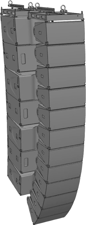
The physical end-fire array comprises 2x or more stacks of subwoofers, positioned one in front of another. Delay is applied progressively to the respective stacks, providing an in-phase summation in front of the array, and an out of phase cancellation behind the array.
Note: Whilst it is technically possible to use different quantities of subwoofers within each stack in the end-fire array, and use gain to match their output with respect to one another, it is not recommended. The stacks will limit at different levels when driven to high SPL’s. This will lead to the cardioid pattern collapsing at higher levels, which is typically when the rear attenuation is most important.
A simple example of a 2-tap physical end-fire array of 3x elements each is shown in [Figure 25]. To determine the spacing of the taps, the following formula is used, the result being the distance of the stacks, grille to grille:
Spacing = Speed of Sound (m/s) ¸ Cancellation Frequency (Hz) ¸ 4 (quarter l)
For a cancellation frequency of 50Hz, the spacing would be 1.72m. [Table 26] shows a reference of common cancellation frequencies and their respective spacings.
| Frequency (Hz) | Spacing (m) |
| 40 | 2.14 |
| 45 | 1.91 |
| 50 | 1.72 |
| 55 | 1.56 |
| 60 | 1.43 |
| 65 | 1.32 |
| 70 | 1.23 |
| 75 | 1.14 |
| 80 | 1.07 |
2.12.3. Electronic Configuration
In this configuration, the standard omnidirectional presets shall be used on all subwoofers within the array, be it with 70Hz, 100Hz (or otherwise) LPF’s. Different LPF Frequencies should not be mixed within the array.
- The upstage-most subwoofers shall all be at zero time.
- The downstage-most subwoofers shall have delay applied, the amount of which shall be determined with the following formula:
Delay (ms) = (1 ¸ Cancellation Frequency (Hz) ¸ 4) * 1000
For a cancellation frequency of 50Hz, the required delay would be 5.0ms.
[Table 27] shows a reference of common cancellation frequencies and their respective delays.| Frequency (Hz) | Delay (ms) |
| 40 | 6.3 |
| 45 | 5.6 |
| 50 | 5.0 |
| 55 | 4.5 |
| 60 | 4.2 |
| 65 | 3.8 |
| 70 | 3.6 |
| 75 | 3.3 |
| 80 | 3.1 |
2.12.4. Acoustic Performance
2.12.4.1. Front SPL
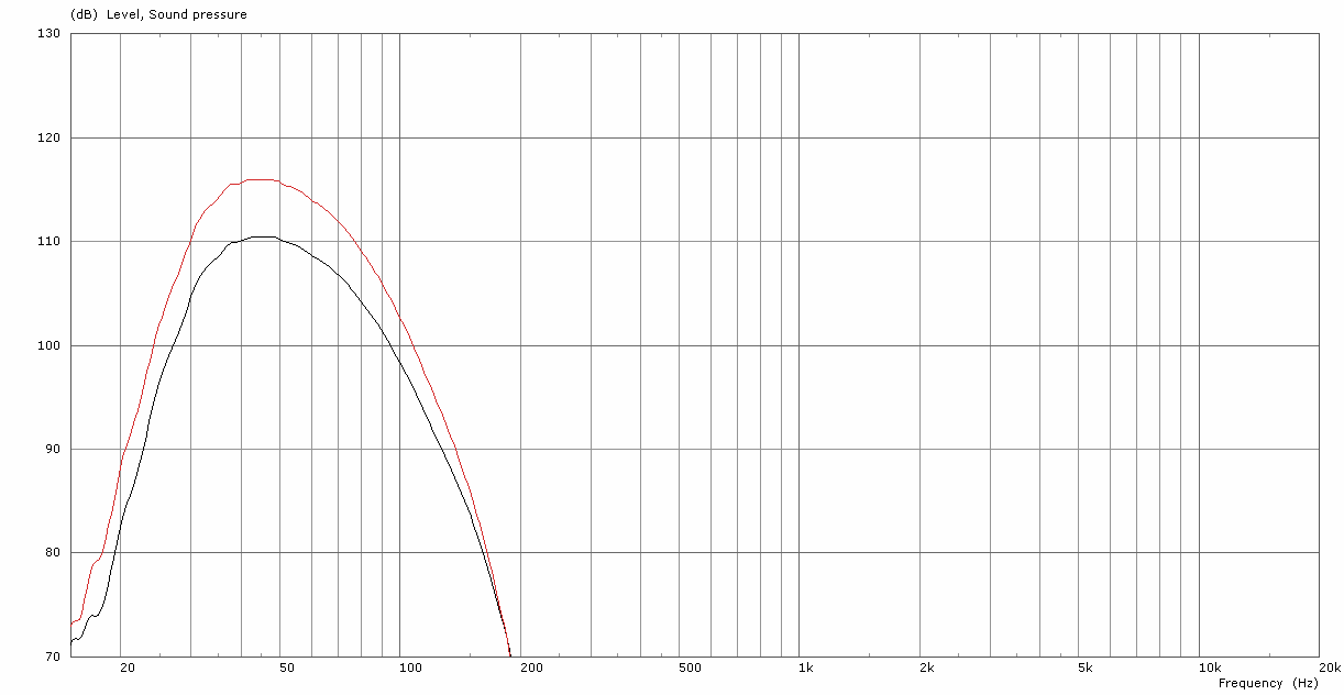
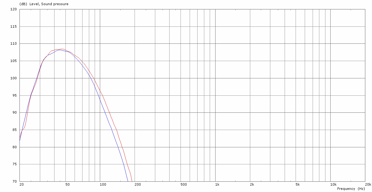
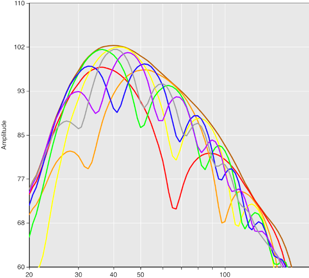
[Figure 28] shows the frequency response of 6x SCP-F’s, configured in a two-tap physical end fire array tuned to 50Hz, measured at 8m. The red trace shows the response of the downstage-most stack of SCP-F’s soloed, and the blue trace shows the upstage-most stack soloed.The downstage-most stack has delay applied to ‘push it upstage’ to the upstage stack – 5ms. The resultant sum of these two sources is shown in the green trace. It can be seen that the frequency response of this array is practically unchanged compared to the reference omni configuration.
2.12.4.2. Rear SPL
The blue trace in [Figure 29] shows the energy radiated rearwards, in comparison to the red trace, which shows the energy radiated towards the front of the array. A significant null can be seen at 50hz, with broadband cancellation either side of this. The delta of these two measurements is shown in [Figure 30].
2.12.4.3. Time Domain Integrity
[Figure 31] shows the individual impulse responses of the upstage and downstage stacks, measured from behind. It can be seen that due to the physical displacement of the individual stacks within the array, there is both a time and level difference. The net effect of this is a strong cancellation rearward .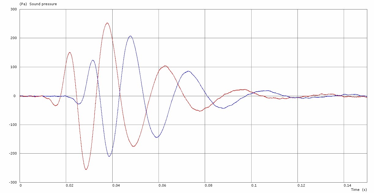
Towards the front, in the direction of the listeners – shown in [Figure 32], the downstage stack (red trace) is time aligned back to the upstage (blue trace), and so a perfect summation can be observed (green trace).
[Figure 32] – End Fire array Time Domain response, in front of array.
2.12.4.4. Directivity
The radiation pattern for the example 2-tap end fire array is shown in [Figure 33].

2.12.5. Analysis
When deployed as suggested, the end-fire array yields an excellent rejection ratio, being large in terms of bandwidth, however it is certainly ‘tuned’ to one frequency in particular. There is no compromise made in step response integrity or efficiency, and the frequency response to the front of the array is hardly changed. The obvious disadvantage of the physical footprint may be an issue, but in some circumstances, it may prove beneficial where there is plenty of space in the upstage / downstage sense, but little in onstage / offstage.
Although the physical end-fire configuration does produce considerable cancellation towards the rear, the cancellation nulls can be very narrow in bandwidth. Adding more taps to the deployment narrows the forward beam-width, and can further increase the reduction ratio, due to the sufficiently staggered arrivals towards the rear, but this is not without its issues – the cancellation is indeed more broadband, but the ripples in the response behind the stack [Figure 34] may prove troublesome for some musicians relying on the reinforcement; some notes may be accentuated, whereas others may not be felt whatsoever.
That being said, with the end-fire configuration, the step response integrity & frequency response integrity towards the front is as good as an omnidirectional subwoofer, and this, coupled with the fact that there is practically no SPL loss compared to an omnidirectional configuration using the same quantity of subwoofers, it is not to be discounted. Even with the ripple in the frequency response to the rear, this is a large reduction in SPL compared to that of the two gradient arrays discussed previously.
2.13. Evaluation of cardioid modes
It can be seen that are several methods at our disposal to create cardioid setups with versatile subwoofers, each with their own benefits and drawbacks. These are summarised in [Table 35] with pseudo ‘ratings’. It is the duty of the system designer to decide how to proceed in any given scenario, where the overriding motive for electing to use cardioid should be balanced with the drawbacks of the selected configuration.
| SPL | Integrity | |||||
| Configuration | Directivity | Front | Rear
Cancellation |
Frequency Response | Step Response | Near Wall? |
| Omnidirectional | ⭐ | ⭐⭐⭐ | ⭐ | ⭐⭐⭐ | ⭐⭐⭐ | ⭐⭐⭐ |
| Standard cardioid | ⭐⭐ | ⭐⭐ | ⭐⭐ | ⭐⭐ | ⭐⭐ | ⭐ |
| Extended cardioid | ⭐⭐⭐ | ⭐ | ⭐⭐⭐ | ⭐ | ⭐ | ⭐ |
| End-fired | ⭐⭐⭐ | ⭐⭐⭐ | ⭐⭐⭐ | ⭐⭐⭐ | ⭐⭐⭐ | ⭐ |
3. Further information & considerations
3.1.1. Interference pattern reduction
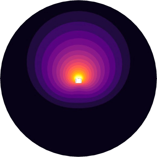
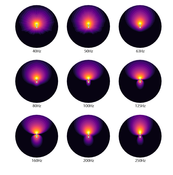
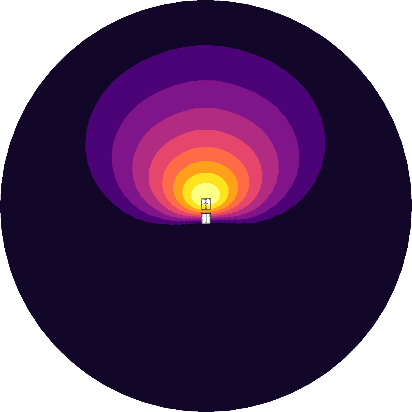
It is a well-known fact that with the typical left / right subwoofer configurations, that there is a pronounced interference pattern in coverage – we are all familiar with the power alley. Without discussing other subwoofer arrangements, and purely extending this left / right configuration using cardioid subwoofer configurations alone, a simple but effective tactic to improve coverage is simply to use the cardioid pattern to our advantage & rotate the subwoofer stacks outwards. [Figures 36 through 39] show a physical end-fire deployment, measured at 30m, with a 5º horizontal angular resolution, at [63Hz 1-Oct]. A marked reduction in the interference pattern can be easily observed.
 |
 |
| [Figure 36] – straight upstage-downstage | [Figure 37] – rotated 35º offstage |
 |
 |
| [Figure 38] – straight – 5º angular resolution | [Figure 39] – rotated – 5º angular resolution |
3.1.2. Non-linearities around limit
The moment that a cardioid deployment of subwoofers goes non-linear, is the moment that the cardioid pattern collapses & we enter the world of the unpredictable. A typical example of when a ‘cardioid-only’ subwoofer may become non-linear is when it contains front & rear drivers of different dimensions / quantity / capability. When pushed hard, at or near limit, differences in behaviour between the forward and rearward facing drivers cause the cardioid pattern to change. Front-facing drivers may have to be made to limit prematurely, to match the limiting characteristics of the smaller rear driver, which is hardly ideal. Using the same subwoofers to create the forward and rearward facing elements of a cardioid array negate this issue, they preserve the cardioid pattern under all circumstances.
3.1.3. The use of cardioid-only or gradient subwoofers in end-fire configurations
The use of cardioid-only subwoofers, or arrays of versatile subwoofers to construct an end-fired array is not ideal. The rearward facing drivers within the arrangement can be seen to work against the forward facing elements of the tap behind. The interaction is complex, but the net result is an overall reduction in the efficiency of the array.
3.1.4. The importance of correct preset recall & cabling
This hopefully does not need be mentioned, but it shall – for completeness sake. It is crucial that when any configuration is chosen, a thorough and methodical process is followed to ensure accurate deployment. Incorrect amplifier preset choice, patching, or misapplication of electronic processing / identification of the incorrect loudspeakers will yield far from optimal results. In some circumstances with a large array of subwoofers, mis-identifying even two elements within the array can completely ruin your day. Dual channel measurement software must be used, to verify the accuracy of the deployment. Naturally, in touring environments, it is strongly encouraged that all panel-work and cabling must be labelled to prevent easily made mistakes, which may prove hard to detect once assembled in larger arrangements.
4. Line Arrays
4.1.What about line arrays? Can they be cardioid too?
In short, yes they can. In much the same way as subwoofers can inherently be cardioid-only or versatile, line arrays can be too.
The radiation pattern of a line array element is the result of many factors, including the enclosure’s material composition, driver configuration, waveguide design, electronic processing applied etc. These factors are not independent of each other, for it is almost never possible to change one without influencing the others; the element’s performance is unquestionably the sum of all its constituent parts.
Note: When we talk about the cardioid radiation pattern, we are talking about the end result. We are simply describing a condition whereby there is measurably less radiated energy to the rear of the element in comparison to the front. We are not talking about whether a line array element incorporates actively driven rear or sideways facing transducers or otherwise. This resultant cardioid radiation pattern can be achieved in a couple of ways.
4.2. Are CODA line arrays cardioid?
Yes and No – whilst our line arrays do not incorporate actively driven transducers whose sole purpose is to provide cancellation towards the rear, our latest line arrays produce an inherent cardioid radiation pattern from circa 200Hz upwards, which is the culmination of many aspects of R&D.
This cardioid pattern is partly realised with our coupler technology, which contributes significantly in a few ways; – not only do the couplers control the mid & high frequency in the horizontal domain, but they crucially also move the horizontal centres of the low frequency drivers much further apart horizontally. Effectively, this makes the loudspeaker artificially larger, horizontally in the acoustic sense, which allows us to maintain the precise directivity down to a much lower frequency than would be possible with elements of their physical size.
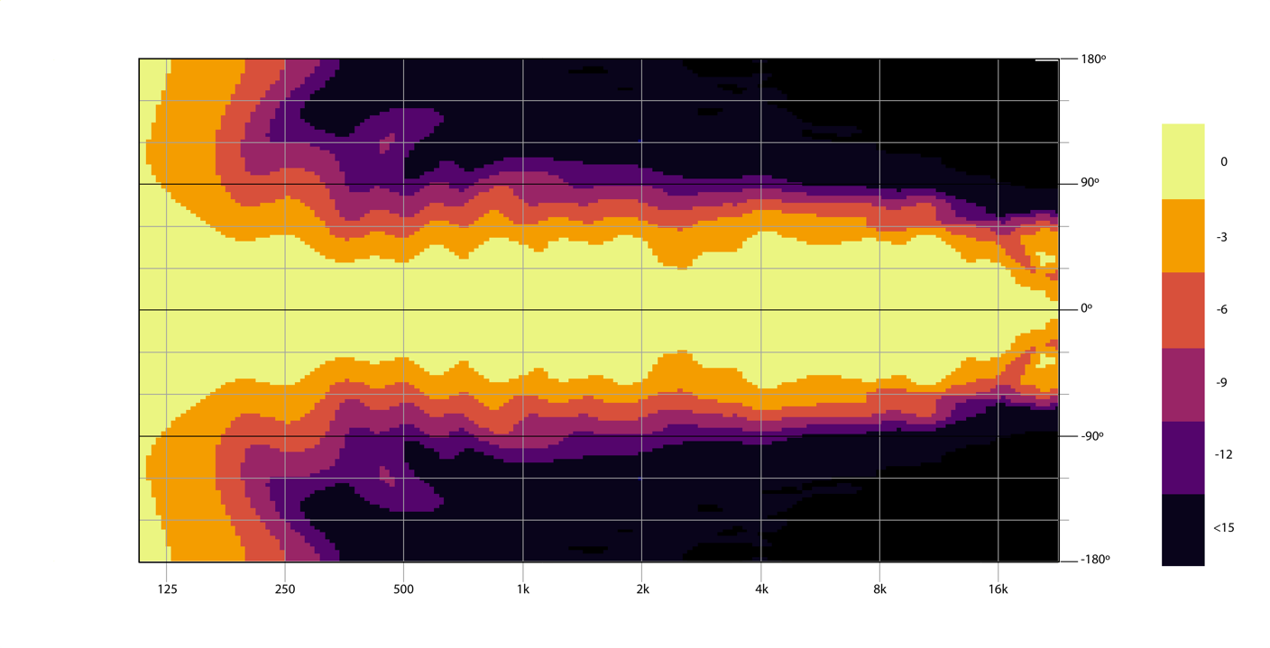
[Figures 40 through 43] show the horizontal directivity of two of our line array elements, the AiRAY, fitted with both 90º & 120º couplers, and ViRAY with both 80º / 120º couplers. It can be seen that these loudspeakers exhibit excellent inherent horizontal control, and can be considered inherently cardioid from say 200Hz upwards, without the use of integral dedicated cardioid drivers.
Note: Don’t just blindly take our word for it, have fun – go and measure this and all other parameters for yourself. Compare enclosures from all different manufacturers, cardioid, or otherwise! If able, use actual loudspeakers and don’t rely solely on proprietary prediction software, pay close attention to smoothing & scaling!
It can be seen however that in the low frequency region, say sub 150Hz, the line array elements are not as ‘cardioid’ as a true cardioid-only system. However, in much the same way as our subwoofers offer many deployment possibilities, this was considered this with our line arrays at the outset of the design stage too.
At CODA Audio as well as line arrays, we also manufacture low frequency extension elements, turning them into incredibly adaptable systems. The low-frequency extensions are by no means an afterthought, nor are they necessary for the satisfactory ‘standalone’ operation of the line array; they are an option which has been engineered in terms of compatibility, both acoustically and mechanically to dramatically increase the versatility of the system.
These low frequency elements can be deployed in a number of ways, some of which result in cardioid radiation patterns to a lower frequency.
4.3. Why doesn’t CODA Audio manufacture cardioid-only line arrays?
Audio quality is one of the main overriding criteria within CODA Audio’s design philosophy. Simply put, “there’s no such thing as a free lunch” when it comes to loudspeaker design, and often there is a balance of compromises. It is outside the scope of this document to fully explain all the justification for this, but in short; to create a line array which is inherently cardioid would be at the expense of (at the very least) the temporal response of the low-mid range towards the front of the element. We consider this would be too great of a compromise, as we pride ourselves in the near-linear-phase nature of our systems, and do not wish to add any compromise with regards to the phase & step response of our line array elements to achieve this inherently cardioid behaviour. The cardioid strategies discussed below preserve the near-linear-phase nature of the system, which not only maintains the interoperability with other system components, but also sounds markedly better.
4.4. How can I achieve a cardioid radiation pattern with my line array?
As can be seen below, with the effective use of our low-frequency extension elements, it is possible to not only seriously increase the low frequency impact & headroom of the system, but also implement cardioid patterns that preserve the excellent near-linear-phase nature of the system.
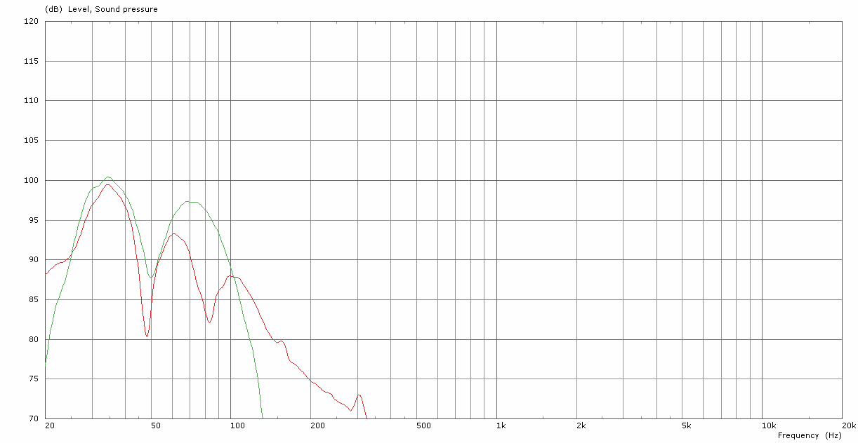
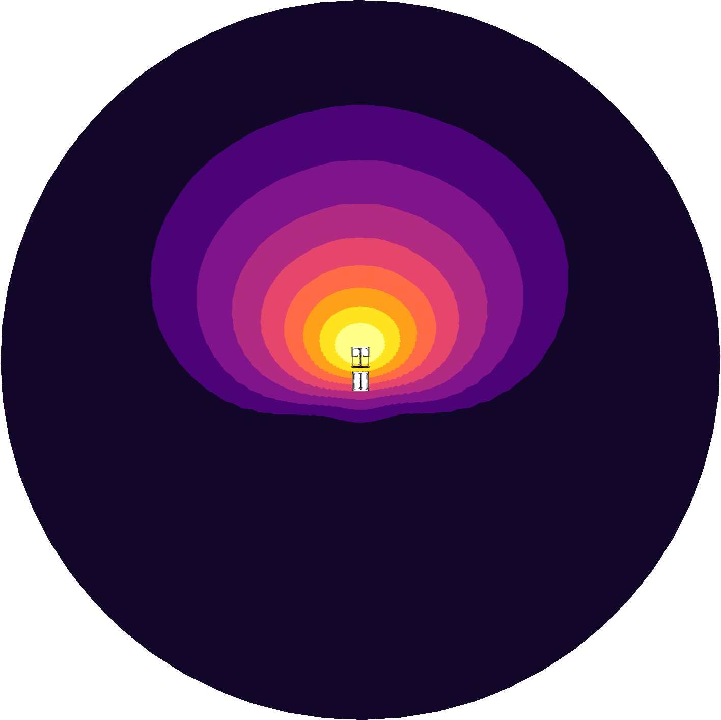
[Figure 44] shows the SPL measured 8m in front of and behind an AiRAY line array loudspeaker – the red trace shows the forward pressure, and the blue trace shows the rearward pressure. The delta of these two measurements is shown in [Figure 45].
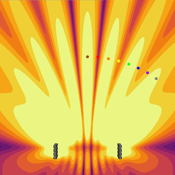
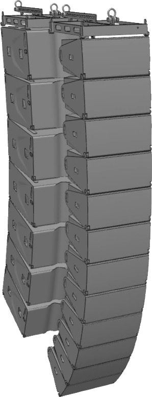
When an array of low frequency extensions is flown behind the line array, it is possible to create either a standard cardioid radiation pattern, or a cardioid pattern with increased rejection. [Figure 47] shows the cardioid radiation pattern obtained when the low frequency elements are flown behind the line array (63Hz @ 1-Oct is mapped). [Figure 48] shows the frequency response in front of and behind these arrays (AiRAY MF / HF are muted). The pink trace is the sum of the AiRAY LF + SC2 8m towards the front, the blue trace being the SC2 soloed, the red trace being the AiRAY LF soloed. The black trace shows the rejection 8m behind the array.
 |
 |
| [Figure 46] – Flown cardioid deployment. | [Figure 47] – Flown cardioid deployment. |
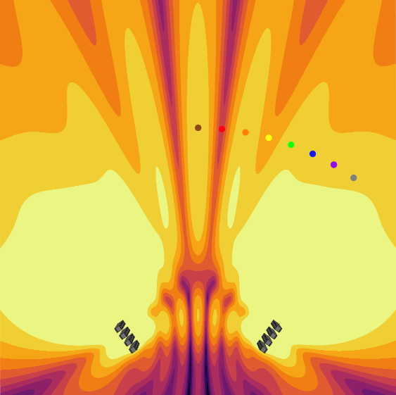
This cardioid deployment can be further tuned towards rear rejection, by rotating every other SC2-F enclosure , and using extended cardioid presets on the SC2-F’s themselves. [Figure 51] shows the enhanced radiation pattern obtained when the low frequency elements are flown behind the line array, however the low frequency extension elements themselves are flown in an extended cardioid configuration (63Hz @ 1-Oct is mapped). An increased rejection ratio can be observed in [Figure 52] when compared to [Figure 48]. Here the frequency response in front of and behind these arrays is shown (AiRAY MF / HF are muted). The pink trace is the sum of the AiRAY LF + SC2 8m towards the front, the blue trace being the SC2-F soloed, the red trace being the AiRAY LF soloed. The black trace shows the rejection 8m behind the array.
 |
 |
| [Figure 50] – Flown Extended Cardioid deployment | [Figure 51] – Flown Extended Cardioid deployment |
4.5. How does the extended cardioid deployment work?
When the low frequency extension is configured in a standard cardioid array configuration (that is, a mix of forwards and rearwards facing elements within one array), then flown behind the line array (as shown in [Figure 50] previously), in effect the whole system is working together to throw the energy forwards, providing substantial wide-band cancellation towards the rear. This configuration is analogous to three sources placed one-behind each other – (line array / low frequency extension front / low frequency extension rear). The horizontal directivity of the entire system remains very consistent over a very wide frequency range.
4.6. Are there any other considerations to the cardioid configuration?
Yes, notably in the vertical domain. It is possible to alter the vertical dispersion pattern of the system simply by altering the trim height of the low frequency elements behind the line array. This is quite complex in nature, but can be extensively modelled offline. The focus of the energy radiated forwards, together with the focus of the rear cancellation can be adjusted, just by adjusting this height.
There are further possibilities with regards to controlling the opening angle with the low frequency elements, both in terms of mechanical angle, and also with tiny incremental progressive electronic delays applied to the individual elements; discussion of which is outside the scope of this document, but the seed should be planted in the mind of the system designer.
All of these possibilities offer great flexibility, which can result in very precise coverage.
4.7. What other deployments are possible with low frequency extensions?
Whilst the cardioid radiation pattern may prove highly beneficial in several circumstances, for instance in:
- reverberant spaces, where the benefit in reducing the diffused energy radiated rearwards would result in a cleaner mix towards the listeners.
- situations where increasing the directivity of the system as a whole would reduce spill between adjacent stages at open-air festivals.
- larger open-air festivals where there is a strong desire to reduce interaction between main and side (aux) hangs, by narrowing directivity and reducing overlap.
There are two other notable configurations possible which provide different results:
- Long throw
- Beam split
4.7.1. LF extension – long throw configuration
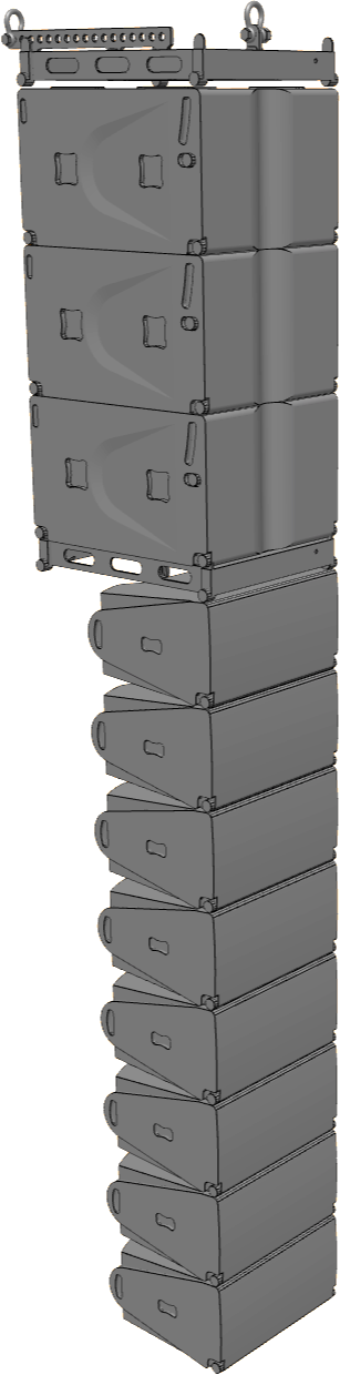
With a taller array comes a narrowing in directivity in the vertical domain. When the low frequency extensions are placed on top of the other line array elements, these extensions overlap typically in the frequency range of range 60-200Hz – (there are slight variations between models). This physical increase in array length enhances the long throw nature of the system at lower frequencies, which provides an overall increase in low frequency energy in the far field.
The main benefit of the long throw configuration is a smaller tonal variation from the front to the rear of a larger audience listening area.
[Figure 53] – Long throw configuration
4.7.2. LF extension – beam split configuration
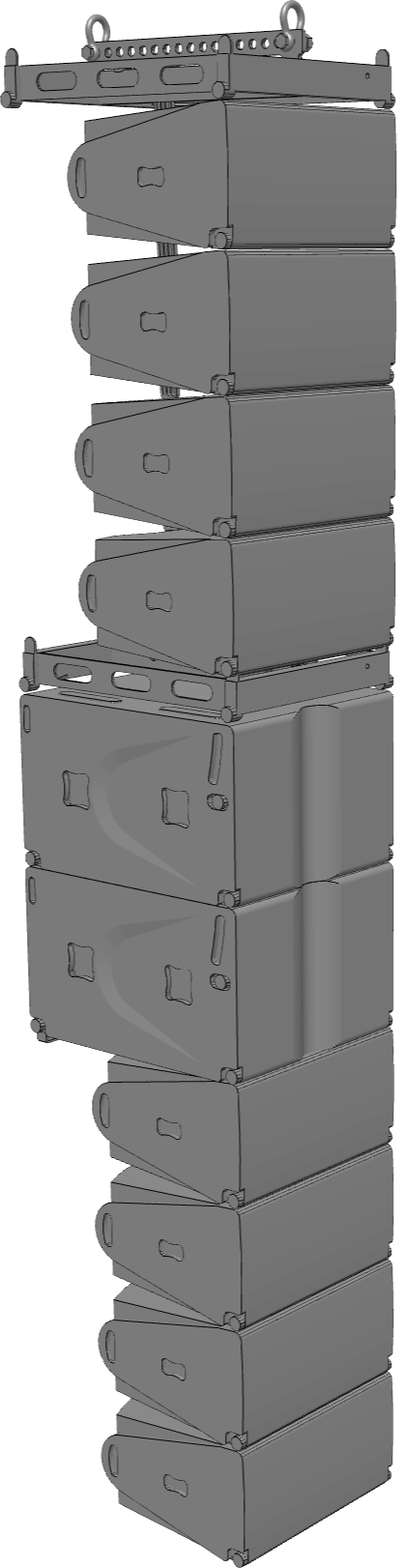
| When the low frequency extension elements are placed between the other line array elements, parts of the vertical dispersion of the system can be split in to two beams with separation between them. This will have the effect of focusing the energy in desirable zones whilst avoiding a hard edge of a balcony in a theatre that would otherwise cause reflections for example.
The low frequency coupling of the line is maintained well, however careful modelling should be performed in prediction software prior to deploying this configuration, to ensure there are no undesirable side-effects in the lower midrange / midrange.
Note: As with all configurations, there is a definite balance of compromise here, it is the responsibility of the system designer to explore the options.
|
[Figure 54] – Beam split configuration
5. Summary
This document does not claim to be an all-encompassing manual, nor is it a substitution for formal training. It merely presents information to empower you in making an informed decision, hopefully presenting both the benefits and drawbacks of certain configurations. Often, the benefits of a given deployment can outweigh the drawbacks, but there have been notable circumstances presented where this is not the case. Loudspeaker system design invariably involves a balance of compromise, and with all practical deployments of cardioid systems, this is certainly true.
‘Cardioid-only’ subwoofers do not only have limited acoustic performance; they also have a limitation in the applications in which they can be used effectively. It has been shown that cardioid-only subwoofers can be near impossible to use in some circumstances. Versatile subwoofers however can be arrayed in omnidirectional, standard cardioid, extended cardioid, end-fire cardioid, and many combinations thereof, offering far more flexibility – allowing them to be adapted to almost any situation.
Within CODA Audio, care has been taken to ensure that as many of our products are compatible with each other as possible, which is something that does not happen by accident. Thorough planning at the design stage is the only way this is possible. This document hopefully shows the versatility of our systems.